Proface LT3300 - 5.7 All-in-One HMI" User Manual
Page 82
Chapter 4 Installation and Wiring
4-15
Interlock Circuit 2
If there is a possibility that the abnormal operation of the LT may lead to an accident, design a fail-safe
measure to configure an interlock circuit with external hardware devices.
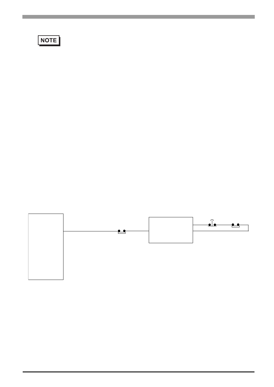
For a system which requires the running motor to stop before all other processes when the travel limit switch
is activated, never design a system in which the signals from the travel limit switch are input to the input
terminals of the LT and then processed using software.
Configure a circuit that reliably stops the running motor using hardware as shown below.
• After executing an internal program, the LT outputs ON/OFF information to the output
devices at the same time. For example, the electromagnetic switches for forward and
reverse rotation of a motor are turned on and off at the same time.
Consequently, a situation may arise in which both of the main contacts of the motor cir-
cuits for the electromagnetic switches for forward and reverse rotation may turn on, caus-
ing a short-circuit of the R and T phases. To avoid this situation, you need to provide the
interlock circuit shown above or use an electromagnetic switch equipped with a mechani-
cal interlock for a forward/reverse circuit.
LT
Running motor control signal
Travel limit switch
Running motor
control circuit
Emergency
stop switch
Travel limit
switch
Direct input to the emer-
gency stop circuit of the
control unit