1 examples of particular i/o connections, 1 examples of particular i/o connections -2, 2 3.1 examples of particular i/o connections – Proface LT3300 - 5.7 All-in-One HMI" User Manual
Page 63
LT3000 Series Hardware Manual
3-2
3.1 Examples of Particular I/O Connections
3.1.1
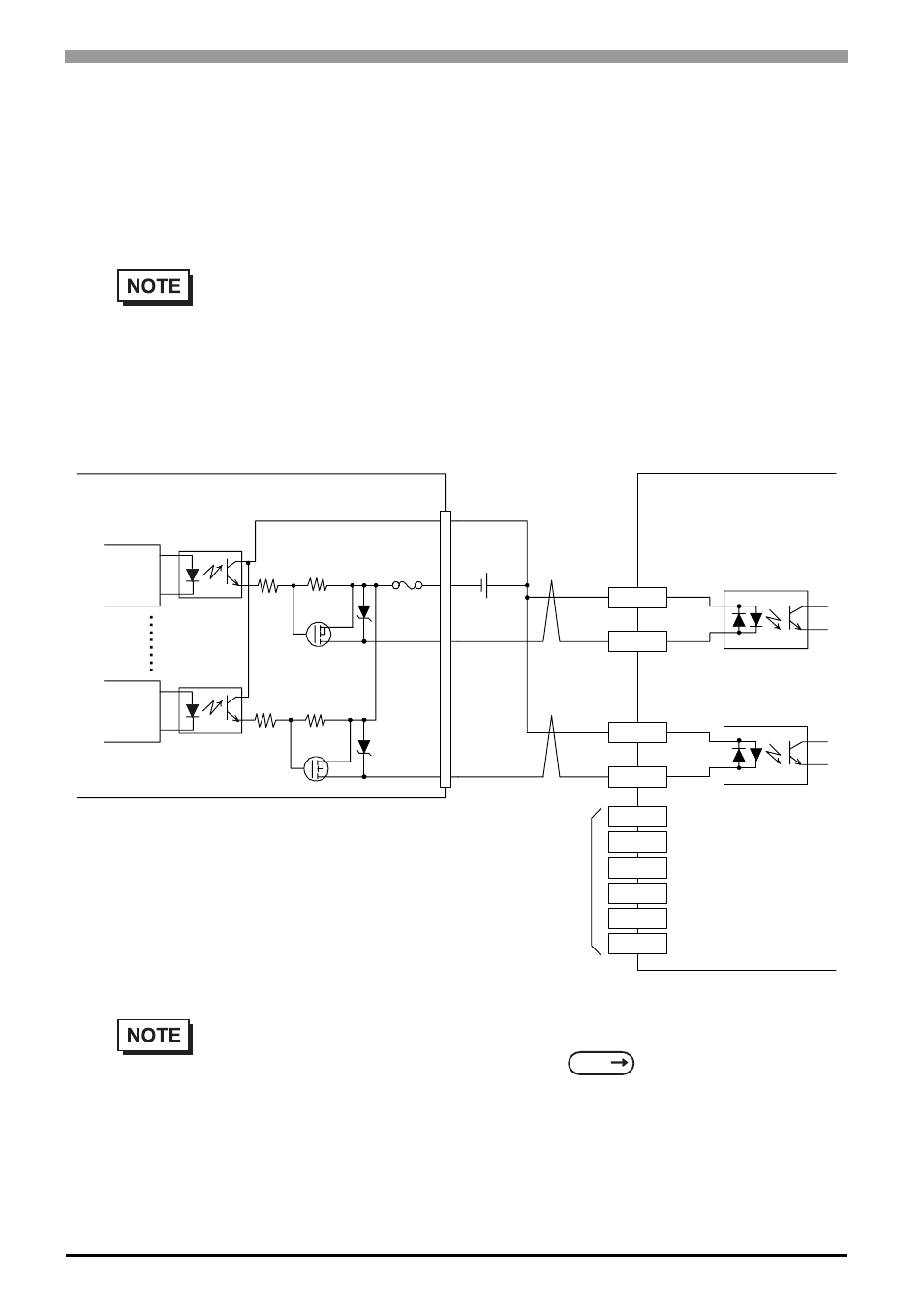
Connection to Pulse Motor Amplifier (CW/CCW type)
The following circuit diagrams show examples of connections between the LT and a pulse motor amplifier (in
the case where the transistor can be connected to the amplifier).
Output Sink Type
• The circuit of the pulse motor amplifier is illustrated by the DC24V CW and CCW con-
cept. However, the withstand voltage and the operating current of the coupler, which
receives pulse signals, vary by manufacturer. Please contact the amplifier manufacturer
before using.
• The output terminals for LT pulses are the ones that have the signal names OUT0, OUT1,
OUT2, and OUT3. For details of the setting,
please refer to the GP-Pro EX
Reference Manual.
Internal
Circuit
Internal
Circuit
Fuse
2.5A
DC 24V
External
Power supply
+24V
LT
Amplifier (DC24V-capable)
Lead wires
from motor
+
-
DIO
0V
OUT0
OUT3
CW A
CW B
CCW A
CCW B
SEE