3 part names and functions, 1 lt-3200 series, 3 part names and functions -10 – Proface LT3300 - 5.7 All-in-One HMI" User Manual
Page 25: 1 lt-3200 series -10, 10 1.3 part names and functions
LT3000 Series Hardware Manual
1-10
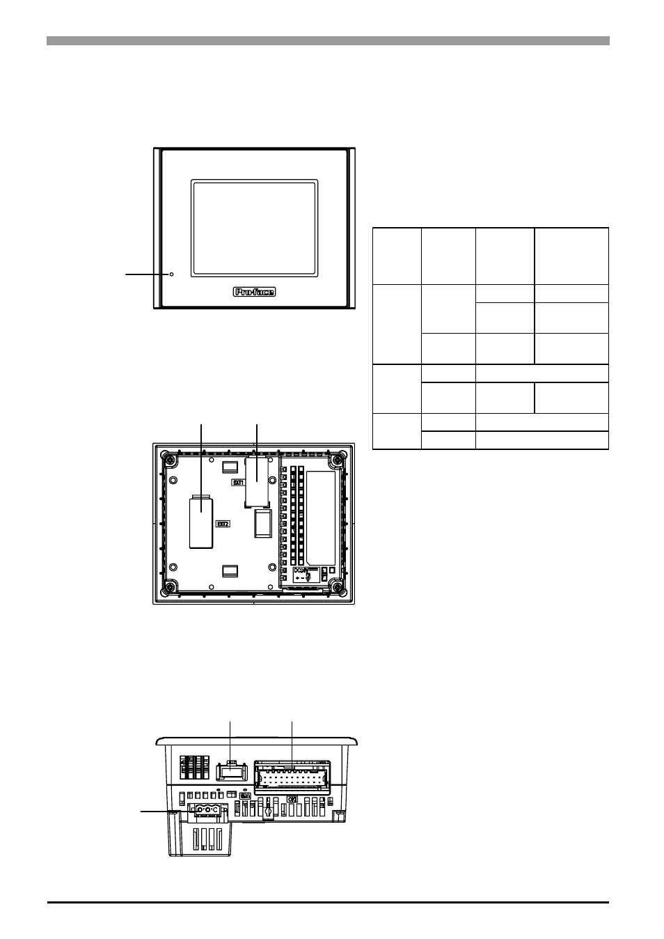
1.3 Part Names and Functions
1.3.1
LT-3200 Series
A: Status LED
This LED indicates the LT’s status, e.g. power
input, firmware RUN status or backlight condition.
Also, indicates the status of logic program
execution.
B: AUX Unit Interface/Expansion Unit (EXT2)
Interface where additional units such as
communication devices can be connected.
C: EX Module Interface (EXT1)
This is the interface to mount the Pro-face’s EX
module.
D: Power Plug Connector
E: USB Host Interface (USB)
Conforms to USB1.1. (TYPE-A conn.)
Power Supply Voltage: DC5V ± 5%
Output Current: 500mA (at maximum)
Connects a data transfer cable or USB-compatible
printer. The maximum communication distance is
5m.
F: DIO Interface (DIO)
This is the interface to mount external I/O
equipment using the DIO connector.
Color
Indicator
Operation
Mode
(Drawing)
Logic execu-
tion mode
(when logic is
enabled)
Green
ON
OFFLINE
-
In
operation
RUN
Flashing
In
operation
STOP
Red
ON
When power is turned on.
Flashing
In
operation
Major Error
Orange
ON
Backlight burnout
Flashing
During software startup
Front
Back
A
B
C
Bottom
E
F
D