3 interface specifications, 3 interface specifications -6, Dio interface (connector) – Proface LT3300 - 5.7 All-in-One HMI" User Manual
Page 33
LT3000 Series Hardware Manual
2-6
2.1.3
Interface Specifications
This section describes the specifications of each interface of the LT Series unit.
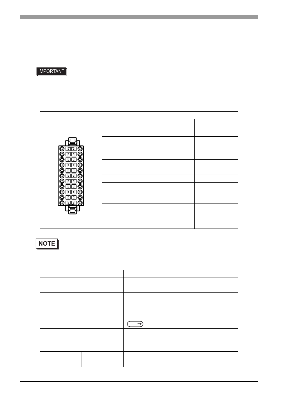
DIO Interface (Connector)
Input Specifications
• When preparing the cable to connect the wiring, check the pin numbers inscribed
on the DIO Connector.
Applicable connector
2-1871940-1
CA6-DIOCN4-01
Pin Arrangement
Pin No.
Signal Name
Pin No.
Signal Name
A1
IN1
B1
IN0 (CT0)
A2
IN3
B2
IN2 (CT1)
A3
IN5
B3
IN4 (CT2)
A4
IN7
B4
IN6 (CT3)
A5
IN9
B5
IN8
A6
IN11
B6
IN10
A7
NC
B7
COM
A8
0V
B8
+24V
A9
OUT1
(PLS1, PWM1)
B9
OUT0
(PLS0, PWM0)
A10
OUT3
(PLS3, PWM3)
B10
OUT2
(PLS2, PWM2)
A11
OUT5
B11
OUT4
• Parenthesized signal names ( ) indicate when Pulse output (PLS*), PWM output
(PWM*), or Counter Input (CT*) are used.
Rated Voltage
DC24V
Maximum Allowable Voltage
DC28.8V
Input Method
Sink/Source Input
Rated Current
6.5mA (DC24V) (IN0, IN2, IN4, IN6)
5mA (DC24V) (Other input)
Input Resistance
Approx. 3.7k
Ω (IN0, IN2, IN4, IN6)
Approx. 4.7k
Ω (Other input)
Input Derating
Input Points
12
Common Lines
1
Common Design
12 points/1 common line
Operation
Range
ON Voltage
DC19V or more
OFF Voltage
DC5V or less
B1
B11
A1
A11
(Cable connection side)
SEE