Maple Systems STEPware-100 User Manual
Page 23
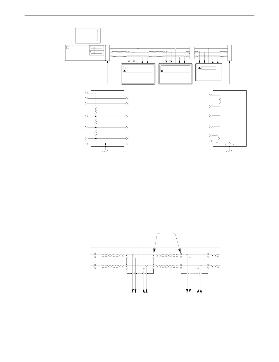
Network Grounding
To communicate properly, serious attention must be paid to the grounding scheme of the
devices connected to the com-link. Improper grounding, improper termination, and faulty
shielding of the com-link are the most common causes of system failure in a multidrop
network.
The cable shield must not be used as the signal ground.
It is tempting to try and reduce the cost of 5-wire cabling by using a 4-wire cable with the
shield used as the signal ground. DON’T DO IT. The initial cost savings are always
exceeded by the maintenance costs once the system is operating under field conditions. It
is often necessary to completely replace the network com-link with the proper cable
(5-wire plus shield) to eliminate noise problems in the system.
The signal ground must not be connected to the chassis or earth ground.
The chassis or earth ground is intended as a safety ground for power supplies, EMI
filters, voltage spike protection circuits, 120 VAC neutral returns, and all manner of AC
and DC driven devices. As a result, the chassis or earth ground can carry large voltage
potentials and currents. Connecting the signal ground to chassis or earth ground can
damage the devices connected to the com-link.
20
STEP1 Protocol Operation Manual
1010-0096, Rev. 04
HOST TERMINATION
470 Ohm
to
10 KOhm
Tx+
Tx-
Vcc
Rx+
Rx-
SIGNAL GND
CHASSIS GND
EARTH
GROUND
TERMINA
TO
R
HOST
OIT3600
120 Ohm
to
240 Ohm
FROM HOST +
FROM HOST -
TO HOST +
TO HOST -
SIGNAL GND
SHIELD
DO NOT
CONNECT
END TERMINATION
470 Ohm
to
10 KOhm
120 Ohm
to
240 Ohm
MAP460D
OIT3160
TERMINA
TO
R
Shield
Signal Ground
From Host +
To Host +
Shield
To OIT
To OIT
Signal Ground
From Host
To Host
From Host -
To Host -