4 jumper settings, 1 at/atx mode select jumper, Umper – IEI Integration KINO-CVR-D25502_N26002 User Manual
Page 57: Ettings, Figure 4-2: jumper locations, Table 4-1: jumpers
KINO-CVR-D25502/N26002
P a g e 45
S te p 4:
Open the SO-DIMM socket arms. Gently pull the arms of the SO-DIMM socket
out and push the rear of the SO-DIMM down. (See Figure 4-1)
S te p 5:
Secure the SO-DIMM. Release the arms on the SO-DIMM socket. They clip into
place and secure the SO-DIMM in the socket.
S te p 0:
4.4 J u m p e r S e ttin g s
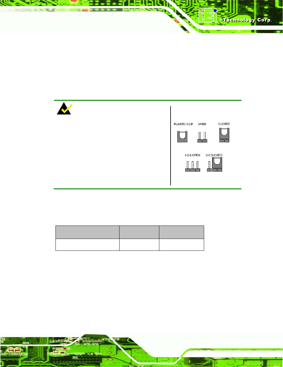
NOTE:
A jumper is a metal bridge used to close an
electrical circuit. It consists of two or three metal
pins and a small metal clip (often protected by a
plastic cover) that slides over the pins to connect
them. To CLOSE/SHORT a jumper means
connecting the pins of the jumper with the plastic
clip and to OPEN a jumper means removing the
plastic clip from a jumper.
Figure 4-2: Jumper Locations
Before the KINO-CVR-D25502/N26002 is installed in the system, the jumpers must be set
in accordance with the desired configuration. The jumpers on the
KINO-CVR-D25502/N26002 are listed in Table 4-1.
Description
Type
Label
AT/ATX mode select
2-pin header
JP2
Table 4-1: Jumpers
4.4.1 AT/ATX Mo d e S e le c t J u m p e r
J u m p e r La b e l:
JP2
J u m p e r Typ e :
2-pin header
J u m p e r S e ttin g s :
J u m p e r Lo c a tio n :