3 external interface panel connectors, Table 4-1: peripheral interface connectors – IEI Integration KINO-945GSE v1.07 User Manual
Page 53
KINO-945GSE Motherboard
Page 37
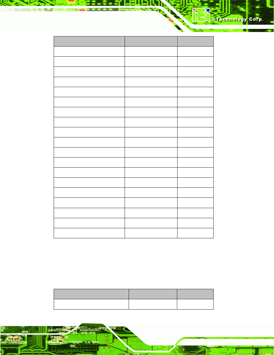
Connector
Type
Label
ATX power connector
20-pin power connector
PWR1
Battery connector
2-pin box header
BT1
CompactFlash® slot
CompactFlash® slot
J2
DDR2 SO-DIMM slot
SO-DIMM connector
DIMM1
Digital I/O connector
10-pin header
DIO1
Fan connector
3-pin wafer
J1
Front panel connector
14-pin header
F_PANEL1
IDE connector
44-pin box header
IDE1
Infrared connector
5-pin header
IR1
LCD backlight inverter connector
5-pin box header
INVERTER1
LVDS connector
30-pin crimp
LVDS1
PCIe Mini slot
PCIe Mini connector
MINI_PCIE1
RS-232 connector
10-pin header
COM3
RS-232 connector
10-pin header
COM4
RS-422/485 connector (COM3) 6-pin
header
JP2
SATA connector
SATA port
SATA1
SATA connector
SATA port
SATA2
TV output connector
6-pin header
TV1
USB connector (2 ports)
8-pin header
USB1
Table 4-1: Peripheral Interface Connectors
4.1.3 External Interface Panel Connectors
Table 4-2 lists the rear panel connectors on the KINO-945GSE. Detailed descriptions of
these connectors can be found in Section 77
7
4.3 on page
7
Type
Label
Audio connector
Dual audio jack
AUDIO1