2 ide disk drive connector (cn1, cn7), 3 floppy drive connector, Figure 4-6: connection of ide connector – IEI Integration ROCKY-3786 v4.10 User Manual
Page 77
Page 77
MODEL NAME
ROCKY-3786EV CPU Card
Page 77
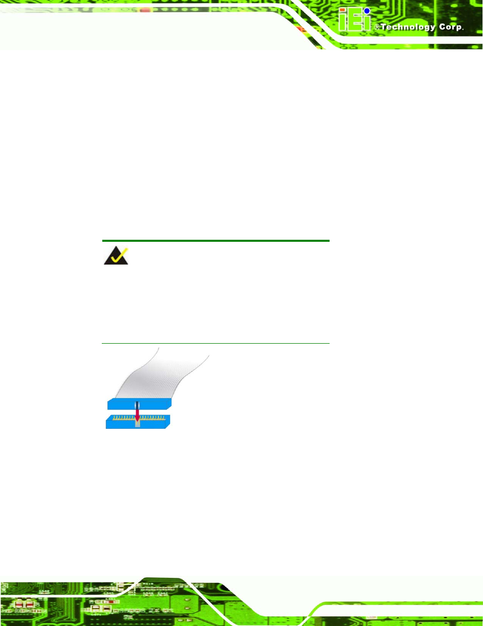
4.3.4.2 IDE Disk Drive Connector (CN1, CN7)
The cable used to connect the CPU card to an IDE HDD is a standard 40-pin ATA66/100
flat cable. Follow the instructions below to connect an IDE HDD to the CPU card.
Step 1:
Find the ATA66/100 flat cable in the kit that came with the CPU card.
Step 2:
Connect one end of the cable to the IDE1 connector on the CPU card. A keyed
pin on the IDE connectors prevents them from being connected incorrectly.
Step 3:
Locate the red wire on the cable that corresponds to the pin 1 connector.
Step 4:
Connect the cable to the HDD making sure that the pin 1 cable corresponds to
pin 1 on the connector.
Step 0:
NOTE:
When two EIDE disk drives are connected together,
back-end jumpers on the drives must be used to
configure one drive as a master and the other as a
slave
.
Figure 4-6: Connection of IDE Connector
4.3.4.3 Floppy Drive Connector
The floppy drive connector provides access to one (1) externally mounted floppy drive.
A 26-pin FPC connector cable is required for the connection to the floppy drive. The cable
should come with a 26-pin FPC-cable connector and floppy disk drive connector on the
other end. Follow the instructions below to connect an IDE HDD to the CPU card.