1 peripheral interface connectors, 1 rocky-3786ev cpu board layout, 2 peripheral interface connectors – IEI Integration ROCKY-3786 v4.10 User Manual
Page 33: Eripheral, Nterface, Onnectors, Figure 3-1: connector and jumper locations
Page 33
MODEL NAME
ROCKY-3786EV CPU Card
Page 33
3.1 Peripheral Interface Connectors
The locations of the peripheral interface connectors are shown in Section 3.1.1. A
complete list of all the peripheral interface connectors can be seen in Section 3.1.2.
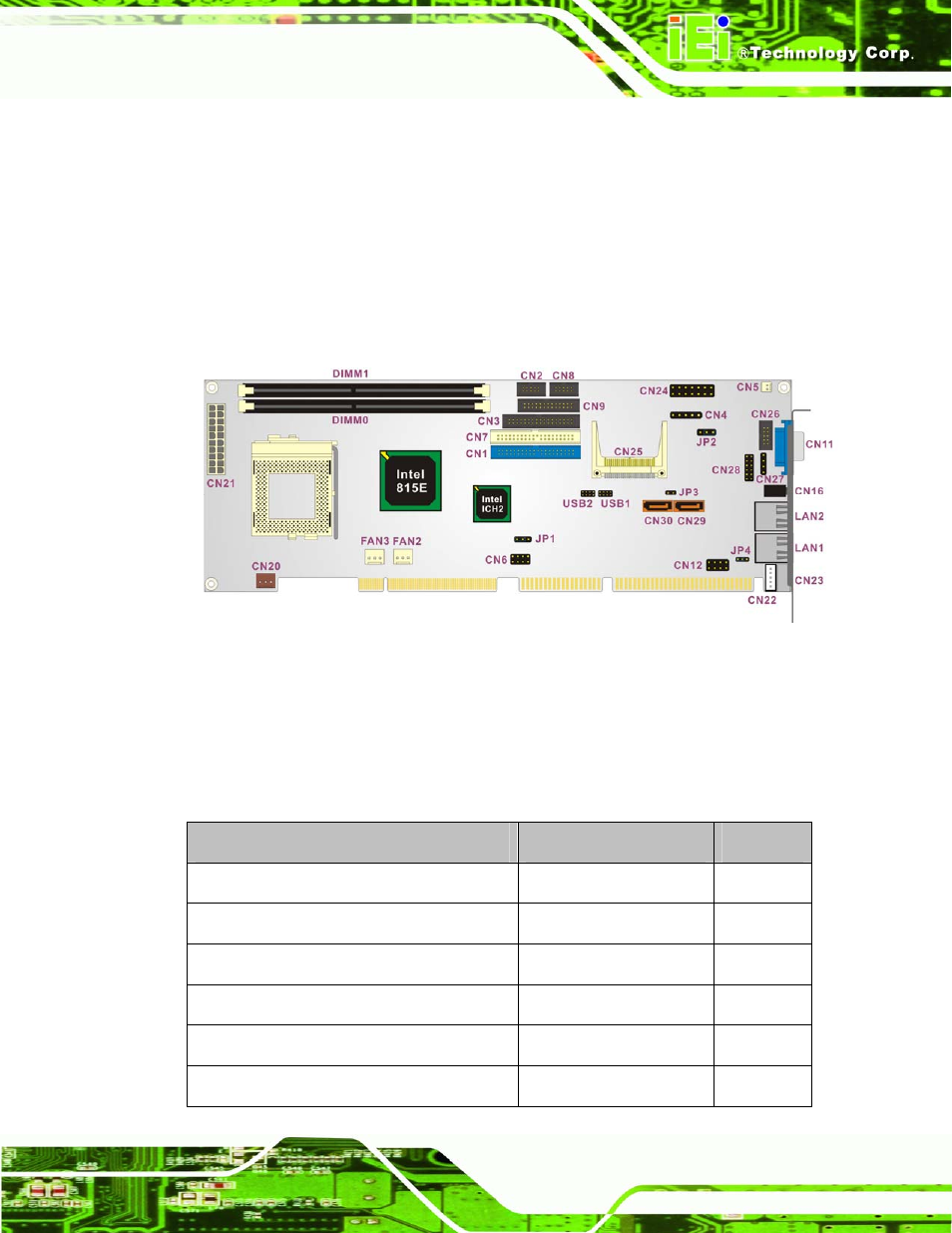
3.1.1 ROCKY-3786EV CPU Board Layout
shows the onboard peripheral connectors, backplane peripheral connectors
and onboard jumpers.
Figure 3-1: Connector and Jumper Locations
3.1.2 Peripheral Interface Connectors
shows a list of the peripheral interface connectors on the ROCKY-3786EV CPU
board. Detailed descriptions of these connectors can be found in Section 3.2.
Connectors
Type
Label
ATX power connector
20-pin header
CN21
ATX power 5VSB and PSON connector 3-pin
header CN20
ATX power switch connector
2-pin header
CN5
Audio connector
12-pin header
CN28
CD In connector
4-pin header
CN27
Compact Flash (CF) slot
50-pin header
CN25