Warner Electric XCTRL-2DRV User Manual
Page 9
Warner Electric • +33 (0) 2 41 21 24 24
P-2097-WE-A4
9
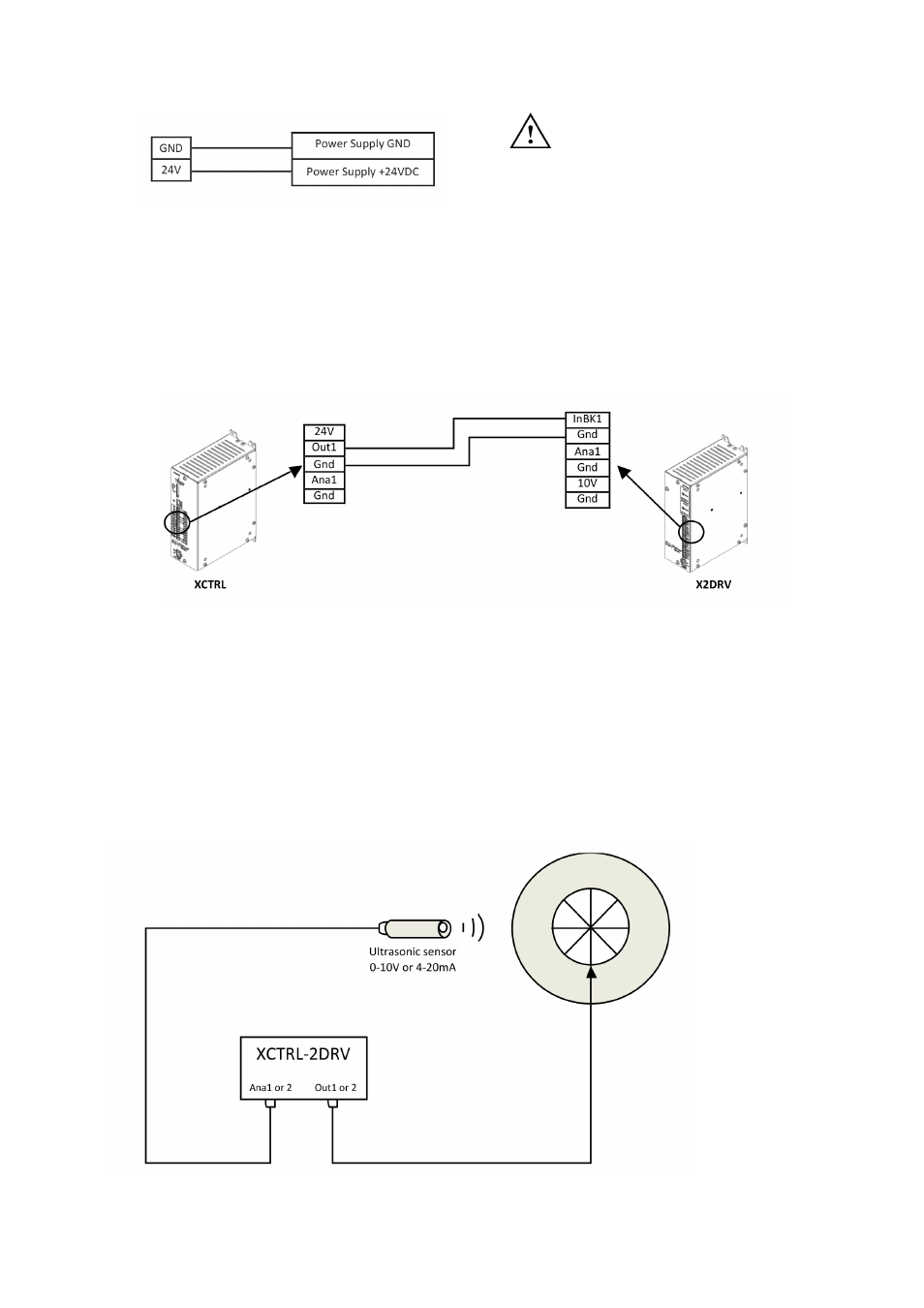
5. Power Supply Wiring
Wire 24VDC input power to pin 24V as shown below:
CAUTION: Improperly setting the
24VDC can damage the power
supply and/or the controller
Figure 9: Power supply wiring
6. Wiring with an X2DRV
If you don’t have an XCTRL-2DRV and you want to get a closed loop control, the XCTRL can be associated
with the X2DRV. For all detail about the driver refer to the X2DRV Installation & Operation manual. The XCTRL
output and the X2DRV Input are selectable (0-10V or 4-20mA). To wire the XCTRL with an X2DRV follow the
procedure below:
Note: 2 Channels available (Out1, Out2, InBK1, InBK2)
Figure 10: XCTRL & X2DRV wiring
Note: When the XCTRL is associated with an X2DRV (XCTRL-2DRV), power supply, input and communica-
tion are made by an internal connector. No connection extra connection between the controller and the driver
is needed.
7. (Optional) Auxiliary analog sensor wiring
Two auxiliary sensor inputs are available. They can both be programmed in 0-10Vdc or 4-20mA type Inputs.
They can also be used with the PID or the Open Loop Controllers input, refer to section 4.d and/or 4.h para-
graph II/ Software Installation and Setting. The most popular use is to have them coupled to a roll diameter
sensor in order to compensate the PID Gain during unwinding
Figure 11: PID Gain Compensation in linear compensation mode
Figure 11: PID Gain Compensation in linear compensation mode