Warner Electric XCTRL-2DRV User Manual
Page 4
4 Warner Electric • +33 (0) 2 41 21 24 24
P-2097-WE-A4
I. INTRODUCTION:
This control is a solid state electronic control that receives signal from a Dancer pivot point sensor or 2 Load cells
and transmits internally the appropriate signals to the brake power driver to regulate a stable tension.
It integrates 2 separate Digital PID controllers and 2 separate Open Loop control. Based on a double board architec-
ture, it can integrate a Driver board to control our electromagnetic brakes range. In that particular case, all communi-
cation, Input/Output and power signal of the driver board will be made thru an internal connector.
All parameters could be saved to an integrated memory and to an SD Card, but can also be uploaded or downloaded
thanks to its external communication bus (USB).
In case of Load Cell application, when the setpoint needs to be modified, an optional handset is available.
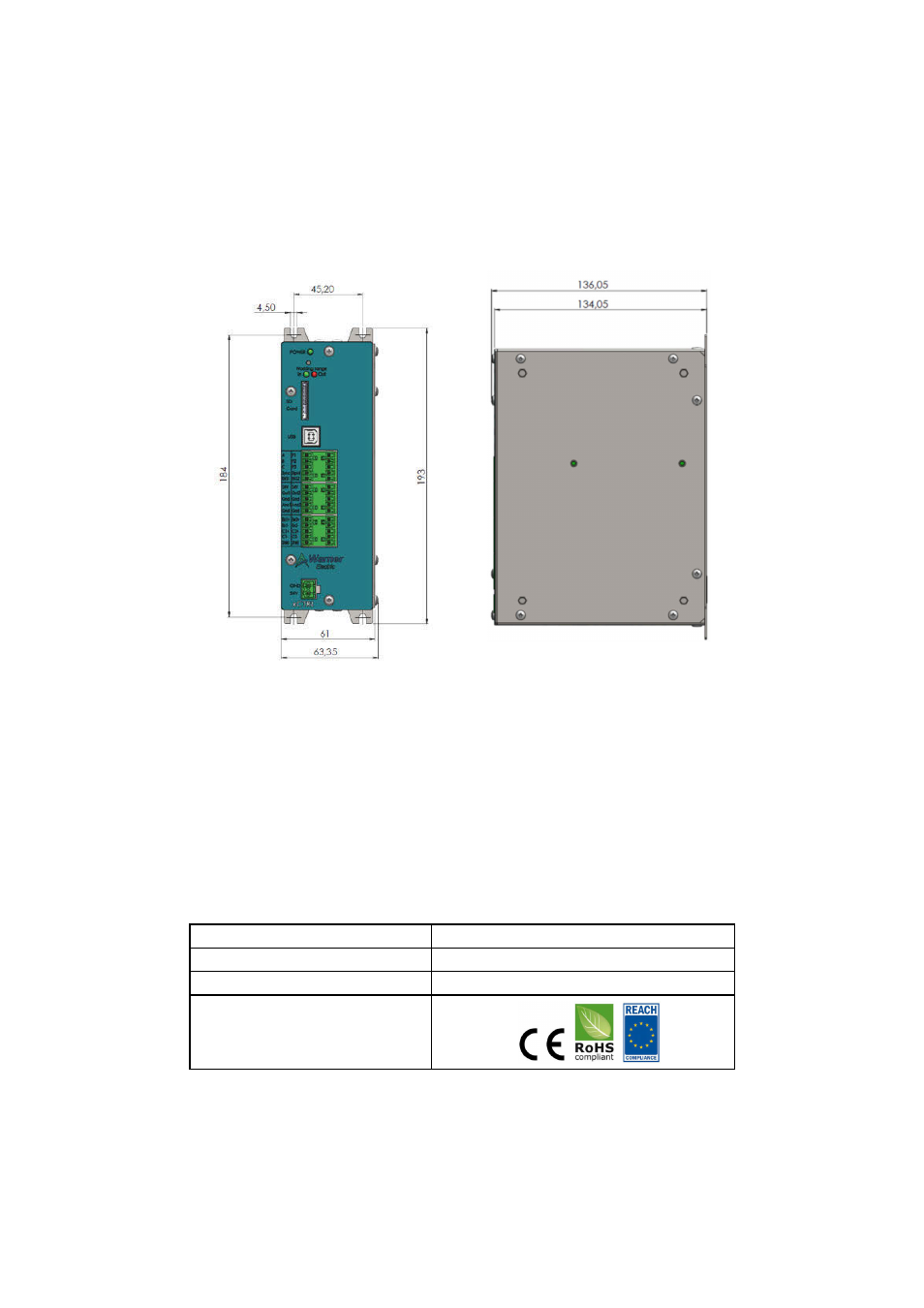
Figure 1: XCTRL Housing Dimensions
II. GENERAL INFORMATION
Control chassis should be kept clear of all areas where foreign material, dust, grease, or all might affect the opera-
tion of the control. Installation must be made in accordance with the instructions found in this manual. Failure to do
so may damage the Controller. Throughout this manual the PID board will be called the XCTRL board and the Driver
board will be called the X2DRV board.
Ratings
Main supply Voltage (V)
24V DC +/- 5%
Output
0-10V and/or 4-20mA
Operating T°C
0°C to 50°C no condensation
Compliance