Warner Electric XCTRL-2DRV User Manual
Page 26
26 Warner Electric • +33 (0) 2 41 21 24 24
P-2097-WE-A4
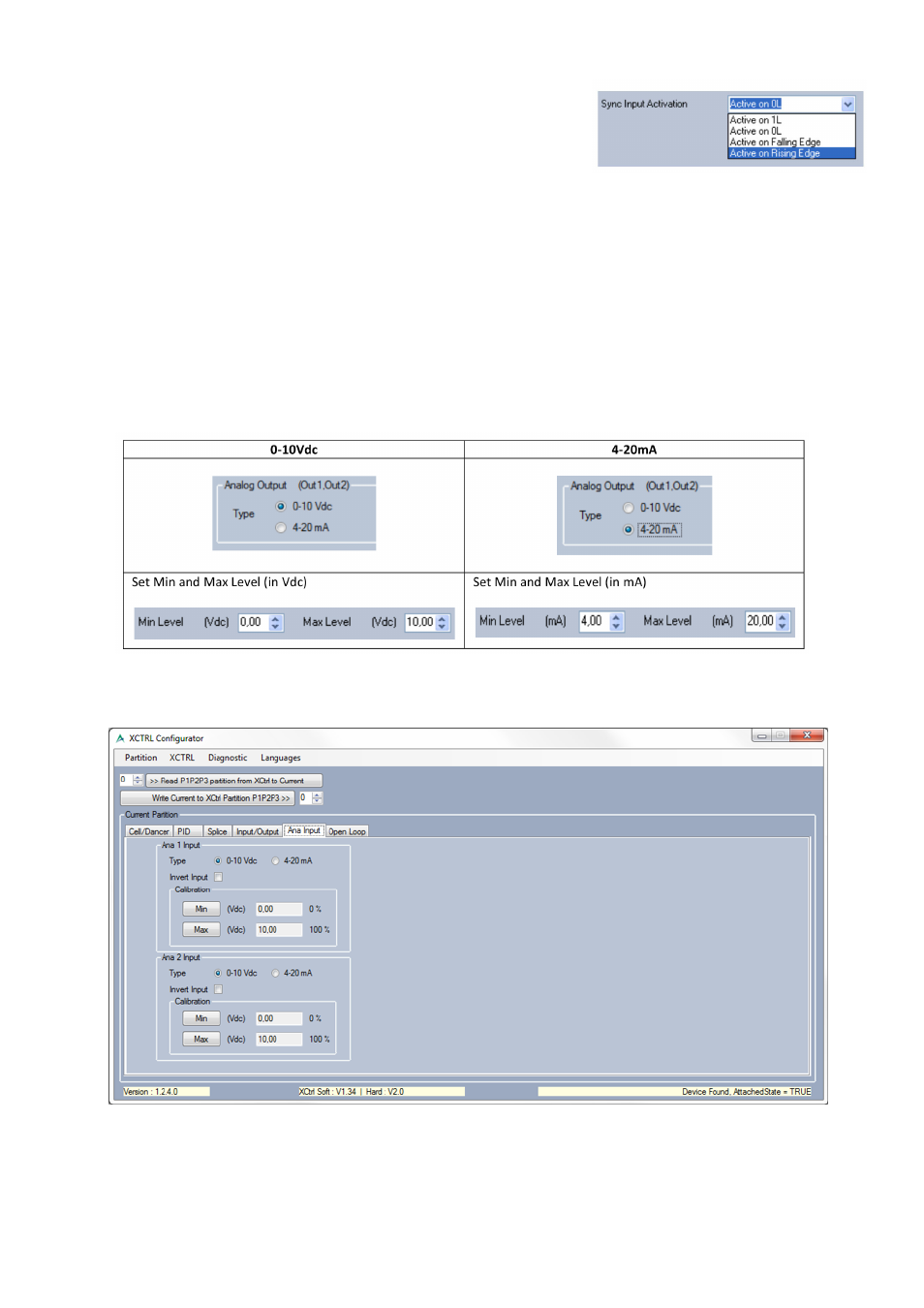
• Sync Input Activation
Active on 1L, active on 0L, active on falling edge or active on rising
edge. For each kind of activation a diagram is displayed on the
software to explain its working.
• Digital Output (ErrS1, ErrS2) settings
The ErrS1 and ErrS2 outputs are used to inform the external application (PLC, Computer,…) that the
corresponding Cell/Dancer Input is out of range. The “Error Range” is defined in the tab “Cell/Dancer”. The
polarity selection is like described above and can be chosen between NPN and PNP.
• The Analog output (Out1, Out2) settings
The Analog output (Out1, Out2) of the controller can be both controlled in voltage (0-10Vdc) or in current
(4-20mA), the selection is straight forward (below picture). On top of that, some absolute voltage/current
levels can be set. These levels will overdrive all logical levels which can be processed by the PID controller or
others.
7. Auxiliary Sensor Setting (Ana Input)
This tab allows you to setup both auxiliary inputs: Ana1 or Ana2. Both inputs can be set in voltage (0-10Vdc)
and in current (4-20mA).