3 the inspector usb box, 1 front panel description, 2 back panel description – Teledyne LeCroy Inspector - Users Manual User Manual
Page 8
CATC
CATC Inspector User’s Manual
Version 2.31
4
2.3 The Inspector USB Box
The Inspector USB box has several user-accessible controls on its front and back panels.
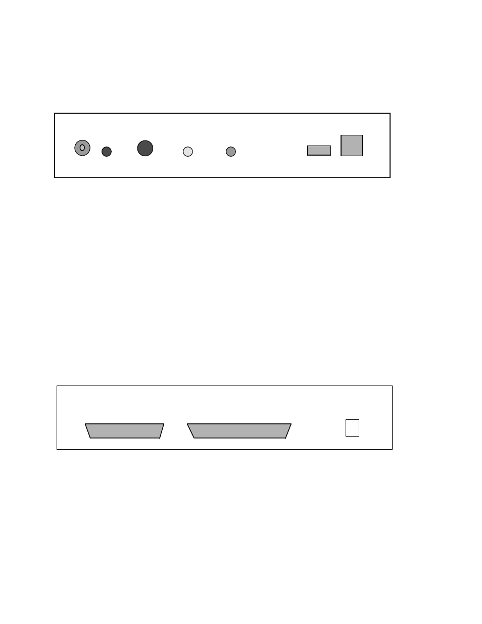
2.3.1 Front Panel Description
The front panel, viewed above, has two USB connectors, three LEDs, and two switches:
•
The four-pin A-type and four-pin B-type USB connectors are marked “USB In/Out”.
•
The red “ON” LED lights when the box is powered by an external 12V DC @ 1A power
source and the power switch is turned on.
•
The yellow “Trigger Event” LED lights when a trigger event has occurred.
•
The green “Recording” LED lights when the Inspector analyzer is recording USB traffic.
•
The “Manual Trigger” push button can be used to manually start and/or end recording
sessions (when enabled in the Recording Options dialog box).
2.3.2 Back Panel Description
The back panel has three connectors:
•
The +12V DC @ 1A input power connector, marked “9–15V DC” (Earlier versions of this
product are marked “9V DC”, but are equivalent in capability).
•
A 25-pin parallel port connector, marked “Enhanced Parallel Port”.
•
A 37-pin external interface connector, marked “Data In/Out”.
Manual
Trigger
Trigger
Event
Recording
Power
USB In / Out
ON
Enhanced Parallel Port
Data In / Out
9–15V