Teledyne LeCroy Inspector - Users Manual User Manual
Page 63
CATC
CATC Inspector User’s Manual
Version 2.31
59
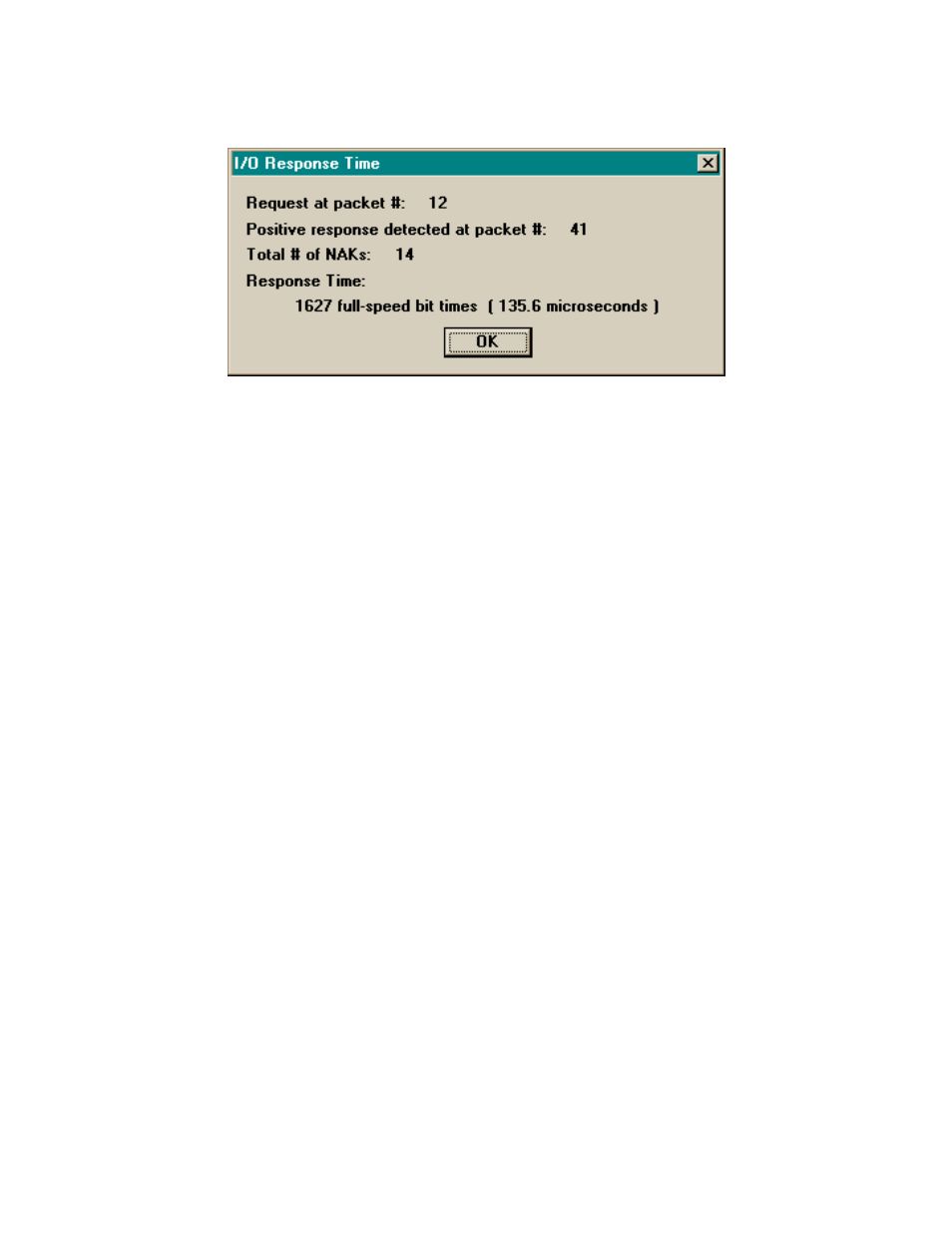
Selecting the “Response Time” menu item brings up the following display, showing the elapsed
time from the selected I/O request and the closest following positive response to same:
5. TRIGGERING LOGIC ANALYZERS AND
OSCILLOSCOPES BASED ON USB TRAFFIC
It is sometimes desirable to capture the internal state of some USB device at the time of a
specific Bus event. This might be something like “one-shot” tracing of a control program with a
logic analyzer upon some error condition, or looking for a logic error by triggering an
oscilloscope every time a specific device or endpoint is addressed. The CATC Inspector tool can
easily be used to produce triggering signals for these operations.
This is facilitated by the External Interface Breakout Board, which provides output pins for (and
thus convenient access to) the configurable trigger signal and those representing pre-determined
USB events, error conditions, and clocking information. All such signals are TTL/CMOS
compatible, low level true.
For the Logic analyzer example above, the analyzer’s Recording Options are set to Event
Trigger, and the desired triggering event(s) specified. These might include a specific Address and
Endpoint or Data String value. When recording is initiated, the CATC Inspector tool will monitor
USB traffic and produce a TRIGGER (out) signal when the desired event occurs. This signal can
be used to start or stop logic analyzers and digital storage oscilloscopes. Traditional analog
oscilloscopes can benefit from a slightly different analyzer setup. Recording Options and Trigger
Selection are as above, but the Post-Trigger Recording selection should be set to Nonstop. This
prevents the analyzer itself from stopping on the selected event, thereby providing TRIGGER
signals upon each occurrence.