KB Electronics KBMK-24DF User Manual
Page 16
16
TABLE 6
KEYPAD DESCRIPTION
Key Description
Starts or Stops the drive.
Changes motor direction.
Up Key: Increases Output Frequency, Set Frequency, Function Number Value, and Code setting.
Down Key: Decreases Output Frequency, Set Frequency, Function Number Value, and Code setting.
Factory programmed to function as a Jog Key. When the key is pressed, it toggles between Run Mode
and Jog Mode (the "JOG/REM" LED will illuminate and the display will show the Jog Frequency Setting
(see Function No. 3.13)). If the key is reprogrammed for Local/Remote Operation (see Function No. 2.02),
the key is used to toggle between Local (Keypad) or Remote Signal Operation (the "LCL/REM" LED will
illuminate).*
*Optional IODA or Modbus is required for Local/Remote Operation.
Used to enter Program Mode and Display Mode. If the key is pressed while Set Frequency is displayed,
the previously entered Function Number will be shown. If the key is pressed while Function Number is
displayed, the Set Frequency will be shown. When more than one display function is enabled, the key is
used to toggle between displays. See Figure 18, on page 19.
Left Shift / Reset Key: Moves the changeable digit or Resets the drive to clear a fault.
Reads or Enters a Function Number's Value or Code setting. The key is also used to read or enter the
frequency setting.
9.3
FLOW CHARTS FOR IMPORTANT PROGRAMMING FUNCTIONS: See Figures 12 – 18, on pages
16 – 19, for flow charts to program important functions. The flow charts also serve as a guide to
understand the programming procedure.
Note: See Table 7, on page 20, for a description of the Digital Readout Codes.
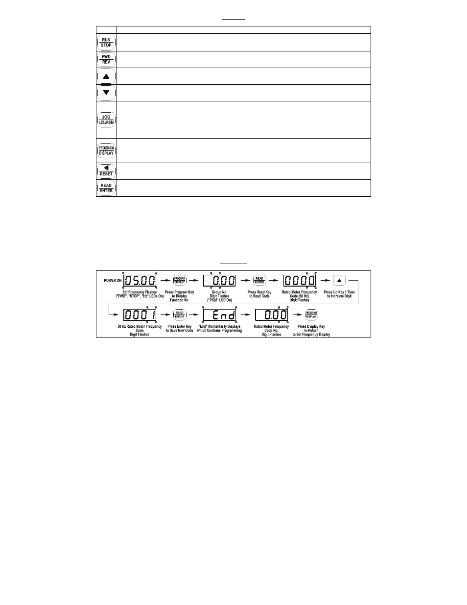
FIGURE 12
FLOW CHART TO PROGRAM THE DRIVE FOR 50 Hz MOTORS