5 external connection diagram, 24 3. installation and w iring – IAI America ACON-CY User Manual
Page 36
24
3. Installation and W
iring
Brown 1
Red 1
Orange 1
Yellow 1
Green 1
Blue 1
Purple 1
Gray 1
White 1
Black 1
Brown 2
Red 2
Red
White
Black
Blue
Orange
Gray
Red
Black
Yellow
Pink
Purple
Orange/
White
Green/
white
Blue/Red
Green
Blown
For teaching pendant/PC
connection
Brake release
switch
ACON-CY controller
Flat cable
External EMG
switch
Input power
supply
24 VDC
Terminal block
24-VDC power
supply for I/O signals
0 V (NPN specification)
24 V (PNP specification)
Load
0 V (NPN specification)
24 V (PNP specification)
Load
Load
Load
Load
Load
Tighten together with a mounting screw.
Motor relay cable
Actuator
Motor
Encoder relay cable
Encoder
Holding brake
Home check
sensor
24 V
0V
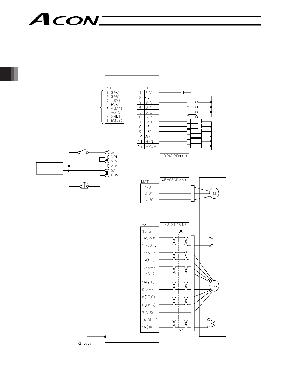
3.5
External Connection Diagram
An example of standard wiring is shown below.
(Note)
The PIO signal names when solenoid valve mode 0 is selected are shown below.
The color of the encoder relay cable is different for the robot cable specification. Refer to 3.9.2,
“Encoder Relay Cable.”