2 name and function of each part of the controller – IAI America ACON-CY User Manual
Page 31
19
6SHFL¿FDWLRQV
2.2
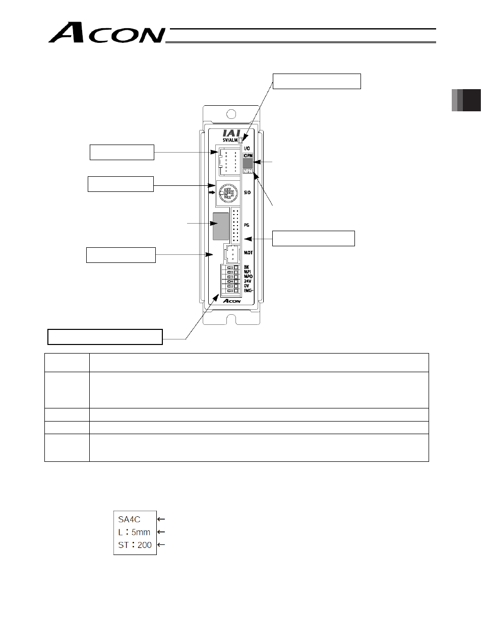
Name and Function of Each Part of the Controller
BK
Connection terminal for the brake forced-release switch to be used when the actuator is
equipped with a brake. Connect the opposite side of the switch to 24 V.
MPI, MPO
Contacts for cutting off the motor drive power to achieve a safety level of safety category 1.
MPI and MPO connect to the input side and output side of the motor power supply, respectively.
(If these contacts are not used, connect them using a jumper cable. The controller is shipped with
MPI and MPO connected by a jumper cable.)
24 V
Positive side of the 24-VDC input power supply.
0 V
Negative side of the 24-VDC input power supply.
EMG -
Connection terminal for the emergency stop circuit (for cutting of motor drive signals).
A common ground is used, so connect the opposite side of the emergency stop switch (or
contacts) to the positive side of the 24-VDC input power supply.
Model indication of the connected actuator type
The type, ball screw lead and stroke of the actuator are indicated. When connecting the cables, confirm that
the actuator is of the correct specifications.
Example of indication:
The actuator type is SA4C.
The ball screw lead is 5 mm.
The stroke is 200 mm.
PIO connector
Connects the PLC and PIO.
Connects the teaching
pendant/PC.
The model of the connected
actuator is indicated here.
Connects the motor cable.
SIO connector
Motor connector
Power-supply terminal block
Status indicator LED
SV (Green) --- Indicates whether or not the
servo is on.
If this LED is blinking, the
controller is in the automatic
servo-off mode.
ALM (Red) --- Indicates whether or not an
alarm is present.
The PIO pattern number is indicated
here.
If the PIO pattern is different for each
system, indicate the applicable PIO
pattern here to prevent confusion.
The I/O signal type is indicated here.
NPN --- Sink type
PNP --- Source type
Connects the encoder cable.
Encoder connector