4 wiring diagram, 56 7. specifi cations – IAI America IX-NNN3515 User Manual
Page 64
56
7. Specifi
cations
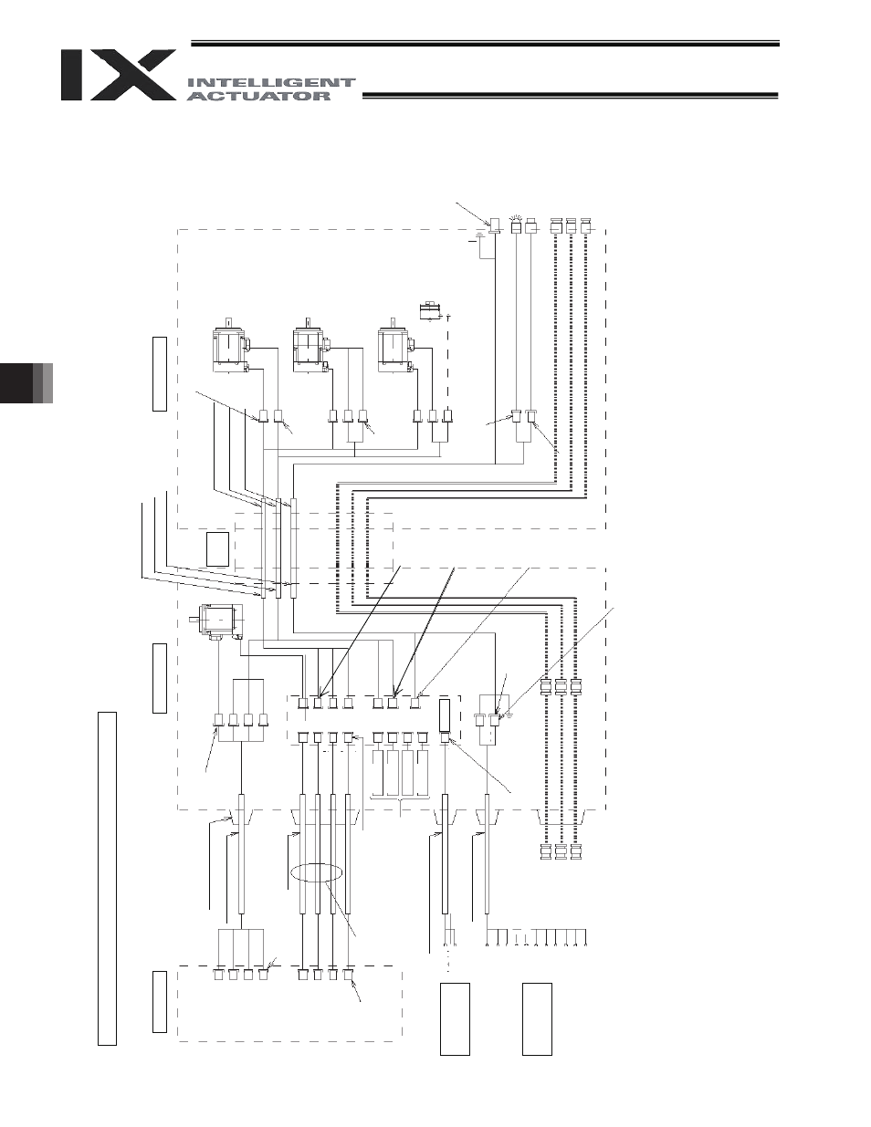
Wiring/Piping Diagram (Arm Length
: 250/350)
Notes
(1)
The actual la
y
out
of board conn
ectors varies from t
h
is draw
ing.
(2)
Since the brake
po
w
e
r circuit is pr
ovided on the p
rimary
side (high-voltage side)
, a dedicated 24 V po
w
e
r suppl
y
is req
uire
d for this circuit.
The 24 V po
wer
supply
f
or I/
O circuits used on the
secondary
side (low
-voltage side) cannot be share
d.
(3)
To operate the al
arm LED, the
user must provide
a circuit that uses the controller I/
O output signal.
7.4 Wiring
Diagram
Controller
Inside
base
F
lex
ibl
e
cable
Inside arm 2
Brake po
w
e
r
terminals
User w
iring
terminals
C
abl
e
fi
x
cap (
C
apc
on)
M cable (o
utside
robo
t)
D
W
G
No.
10
687
63*
Socket
172
159-
1
(T
y
c
o Electronics
AMP
)
S
e
rv
o
m
o
to
r
fo
r
a
x
is 1
(a
rm
1
)
D
W
G
N
o.
10
694
43*
PG ca
ble (
inside
robo
t)
M cable (insid
e rob
o
t)
U cable (insid
e rob
o
t)
Socket
DF11-8DS-2C (Hirose)
S
e
rv
o
m
o
to
r
fo
r
ax
is 2 (arm
2)
Socket
172
159-
1
(
T
y
c
o
Electronics AMP)
Ser
v
o mot
or
w
ith
br
ake
for
ax
is
3
(Z-axis)
Socket
172
157-
1
(
T
y
c
o
Electronics AMP)
S
e
rv
o
m
o
to
r
fo
r
ax
is 4 (R-axis)
Electromag
netic
br
ake
for
ax
is
4
(R-axis)
(Optional)
D-sub con
nect
or
X
M
2D
-1501
(O
mr
on)
FG (
to D-
sub
ho
using
)
So
cke
t DF3
-2
S-2
C
(Hiro
se
)
D-
su
b
c
o
n
n
ec
tor
for
u
s
e
r w
ir
ing
(
15-
pi
n
, s
o
c
k
e
t)
Al
ar
m L
E
D
Brake-releas
e sw
itch for ax
es 3/4
(Z/R-ax
es)
So
cke
t DF3
-3
S-2
C
(Hiro
se
)
Air joint, bl
ack (
I
4)
Air jo
in
t, re
d (
I
4)
Air joint, w
h
ite (
I
4)
Pl
ug
172
166-
1
(T
y
c
o Electronics
AM
P)
Socket
DF11-10DS-2C (Hirose)
Air joint, bl
ack (
I
4)
Air jo
in
t, re
d (
I
4)
Air joint, w
h
ite (
I
4)
Pl
ug
D
F
11-
10D
EP-
2C
(Hir
ose)
FG (
T
o
bas
e)
C
onnec
tor
XA
P
-0
2
V
-1
(JST
)
Boar
d
PG ca
ble
(outside r
obo
t)
Femal
e co
nnec
tor
HIF 3BA-1
0
D-2,54C
(Hir
ose)
DW
G
N
o
.
106
876
4*
BK p
o
w
e
r cable (
o
u
tside r
o
b
o
t)
U cable (o
utside
rob
o
t)
Dedicate
d b
a
tt
eries
fo
r IX
: AB-3
D
W
G
No.
10
687
65*
Housing
KEC
-15P
Contact
JK
-S
P
2
14
0
(JST
)
Pl
ug
GIC2,5/
4-S
T
F-
7,62
(
P
ho
eni
x
Contact)
M1
M2
M3
M4
PG
1
PG
2
PG
3
PG
4
M1
M2
M3
M4
PG
2
M2
PG
3
M3
BK
3
PG
4
M4
BK
4
LED
BK
User
Conn
ec
tor
ALM
BK S
W
INPG
1
INPG
2
INPG
3
INPG
4
OUT
P
G1
OUT
P
G4
BK
4
BK
3
OUT
P
G2
OUT
P
G3
SW
BAT
1
BAT
2
BAT
3
BAT
4
24 V
DC
UA
UB
+24
V
G
24 V
U1
U2
U3
U13
U14
U15
LED +2
4V
LED G
2
4V
FG
D
W
G
N
o.
10
694
42*
D
W
G
N
o.
10
694
44*
Pl
ug
172
165-
1
(T
y
c
o Electronics
AM
P)
Pl
ug
172
169-
1
(T
y
c
o Electronics
AM
P)