54 7. specifi cations – IAI America IX-NNN3515 User Manual
Page 62
54
7. Specifi
cations
IX
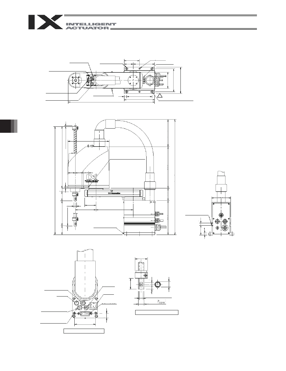
NNN 3515 (Arm Length 350, Standard Specification)
ALM (indicator)
I 4 quick air-tube joint
(black, red, white; 3 locations)
User connector
(D-sub 15-pin connector)
BK SW
(Brake-release switch)
Arm 2 stopper
Reference surface
Arm 1 stopper
2 4-
I9
I 16, counterbore depth 0.5
4 (
M
echa
ni
cal
e
nd)
4 (
M
echa
ni
cal
e
nd)
Tapped hole for peripheral
installation (4-MA, depth 12)
Same on opposite surface
T-slot for peripheral
installation
(M3, M4)
I 4 (red) quick joint
ALM (*2)
I 4 (black) quick joint
Spacer user part installation
Outer diameter
I 7, height
10, M4, depth 5 (*1)
I 4 (white)
quick joint
I 11 (inner diameter)
I 16h7
Detailed view of panel
Detailed view of arm tip
*1: External force applied to the spacers must not
exceed 30 N in the axial direction or 2 N
m in the
rotating direction (for each spacer).
*2: The LED operates only when the user provides a
circuit that receives controller I/O output signal and
supplies 24 VDC to the LED terminal in the user
connector.
92.5
55
2-
I8H10
130
(524.5)
100
185
140
160
155
15
249.5
372.
5
44.5
50
30
(164)
250
(694)
74
206
21
55
ST150
54
I16
68
125
225
60
15
12
120
652.
5
8
15
10
30
8
12
I35
BK SW
User
Connector
57
Reference surface