IAI America IX-NNN3515 User Manual
Page 60
52
7. Specifi
cations
s
n
o
i
t
a
c
i
f
i
c
e
p
S
m
e
t
I
Surrounding air temperature/humidity
Temperature: 0 to 40 C, humidity: 20 to 85%RH or
less (non-condensing)
Operating
environment
Altitude
m
1,000 or less
1
7
B
d
e
s
i
o
N
Robot weight
kg
18.2
Power supply
230 V
50/60 Hz
5 A
Allowable supply voltage
fluctuation
%
10
Overvoltage category (IEC60664-1)
Category III
Controller
Pollution degree (IEC60664-1)
Pollution degree 3
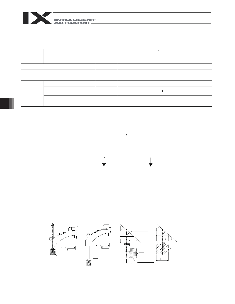
*1 To move the robot horizontally at high speed, perform teaching so that the vertical axis stays as close to the
top position as possible. (Fig. 1)
To operate the robot with its vertical axis at the bottom position, the speed and acceleration must be
reduced as appropriate. (Fig. 2)
*2 Assuming PTP instruction operation.
*3 Measured at a constant surrounding air temperature of 20 C.
*4 Measured when the robot is operated at the maximum speed, carrying a load of 2 kg.
This cycle time assumes a reciprocating operation involving a vertical travel of 25 mm and horizontal travel
of 300 mm. (Rough positioning)
*5 A force of up to three times the dynamic push-in thrust may be applied at any given moment.
*6 “Static” thrust means a thrust generated within the range of operation effected by a PAPR command (push-
motion approach distance, speed setting).
*7 The permissible moment of inertia converted to a value at the rotational center of axis 4. The offset from the
rotational center of axis 4 to the tool’ s centerof gravity is assumed to be 40 mm or less. (Fig. 3)
If the tool’ s center of gravity is fu
rther away from the rotational center of axis 4, the speed and acceleration
must be reduced as appropriate.
*8 If the tool exceeds the permissible diameter, it will contact the robot inside the robot’ s range of movement.
(Fig. 4)
*9 To enable the alarm LED indicator, the user must provide a circuit that supplies 24 VDC to the LED terminal
in the user connector in response to the controller I/O output signal, etc.
Reference design standards: Annex I to Machine Directives, EN292-1, EN292-2, EN1050, EN60204-1, EN775
Note: Continuous operation at the
maximum speed is not feasible.
25 mm
300 mm
Top position
Tool
Bottom
position
Tool
Center of
rotational axis
Tool
40
Tool’ s center
of gravity
Tool
Center of
rotational axis
80
(Fig. 1)
(Fig. 2)
(Fig. 3)
(Fig. 4)
Brake power source for main unit
W
24V DC ±10%
20W