Gentec-EO Beamage-M2 User Manual
Page 24
Beamage-M
2
User Manual Revision 2.0
24
Figure 3-16 Internal Adjustment Screws of the Beamage-M2 Module
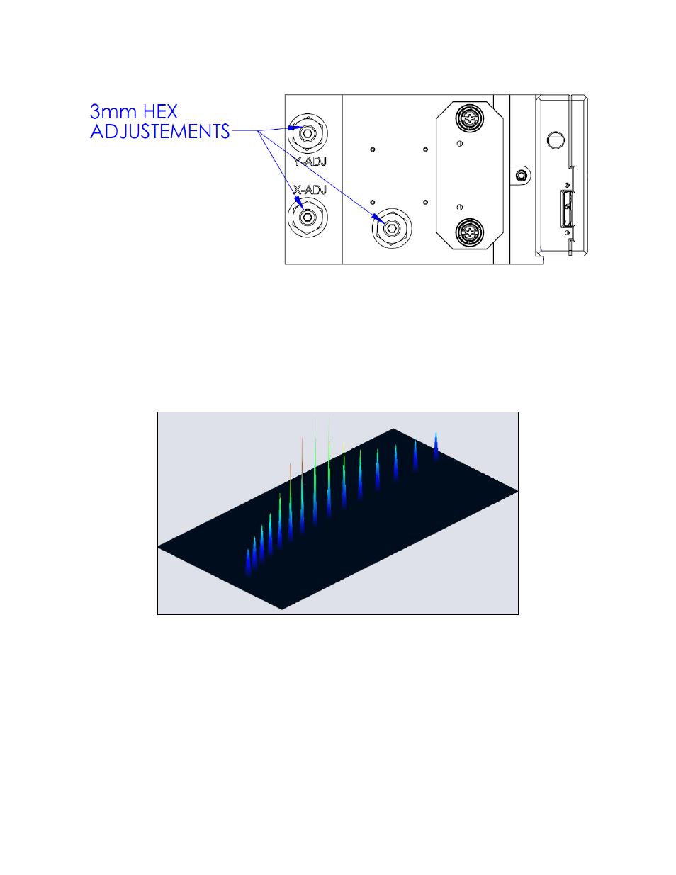
4- The system is correctly adjusted once you see a profile similar to the figure shown below. A narrow and
tall spot should be surrounded by smaller and larger spots.
5- For ISO compliant calculations, at least 10 spots should be detected. Approximately half of the spots
should be distributed on one Rayleigh length around the beam waist and the other half should be
distributed between one and two Rayleigh lengths around the beam waist.
Figure 3-17 Spots Seen with a Correctly Aligned Setup