Practical measurement, Abry, Erot – Gentec-EO Beamage-M2 User Manual
Page 12: Nterferometer, Figure 2-2 schematic of the fabry-perot optics
Beamage-M
2
User Manual Revision 2.0
12
2.1.2. Practical Measurement
In order to measure the M
2
factor, multiple slices of the beam within and beyond one Rayleigh length along the
propagation axis must be considered. For each one, the second order spatial moment beam radius w(z) is
measured. A hyperbola, which recalls the beam radius equation, is then fitted with the results. The M
2
value is
derived from that fit.
Since the distance range within which the measures must be taken is too large (could be several meters), the
use of a focusing lens is mandatory. It is also mandatory to comply with ISO standard. It helps compressing the
slices of interest around the focal spot of the lens.
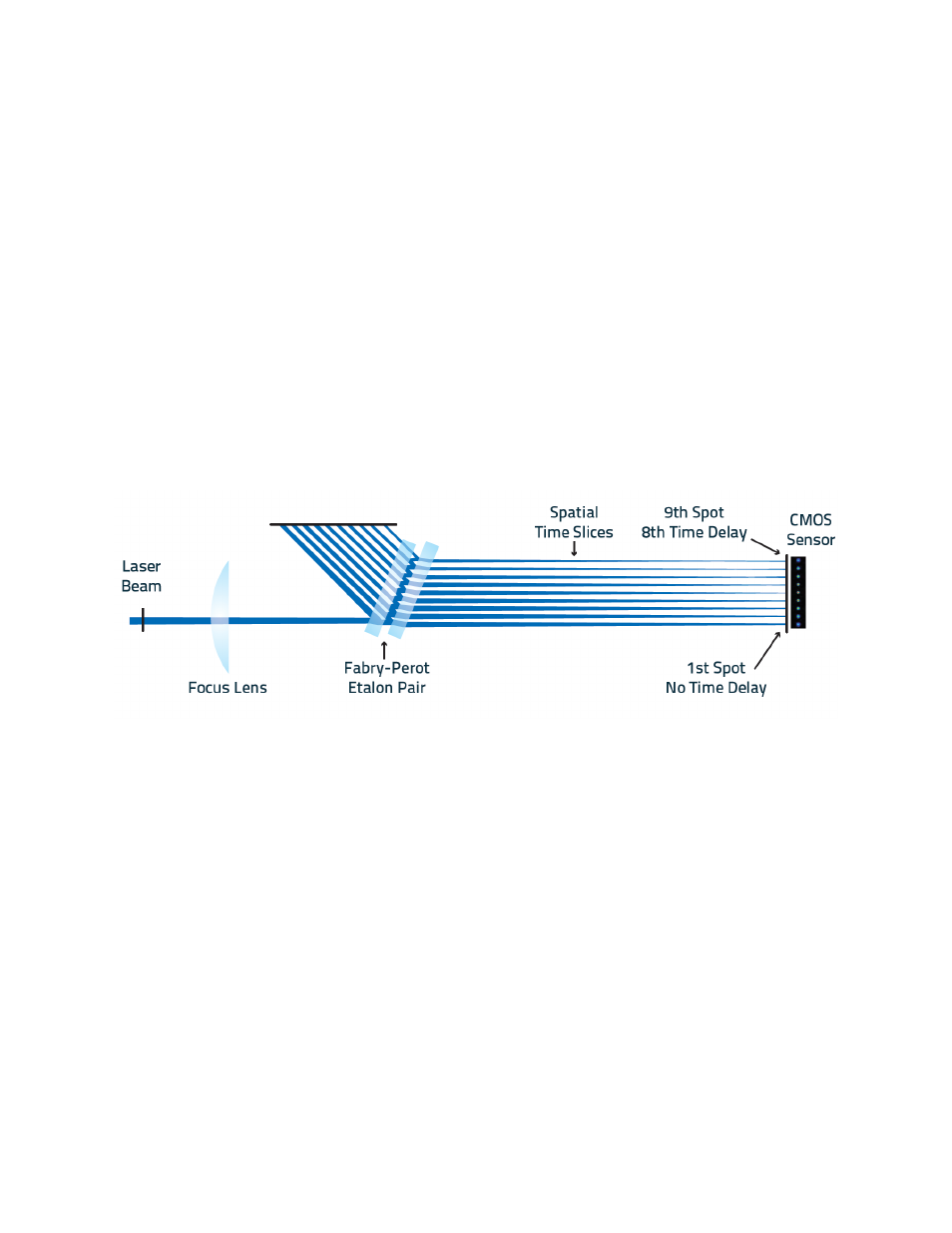
2.2. The Fabry-Perot Interferometer
Within the device, the rapid measurements are done with the use of a completely passive optical system. Inside
the device, a pair of Fabry-Perot etalons, which is in fact an interferometer made of a pair of partially reflective
glasses, is positioned in front of the CMOS sensor of the camera at a convenient angle for the light to oscillate
and, with each round trip of the focused laser beam, creating a time-delayed and spatial offset of the light.
Figure 2-2 Schematic of the Fabry-Perot Optics
The adjustable distance between the Fabry-Perot etalons allows the measurement of beam waists for a large
range of focal lengths. Measurement is possible for any system that uses a lens with a focal length equal to or
higher than 110 mm. For shorter focal lengths, a focusing adapter is required. It can be mounted onto the
entrance port of the system.
Multiple time-delayed slices of the beam will land on the CMOS sensor, each one being a spatial cross-section
along the waist which is evaluated as a region of interest (ROI). The software will then simultaneously image and
analyze them for unparalleled speed and accuracy of M
2
value calculation. When used at its highest resolution,
the Beamage-M2 works at 11 frames per second divided by the number of beams measured. This results in a
measurement of the M
2
factor in about 1000 milliseconds. Adjustments can be made for the exact beam waist
to be contained within the multiple regions of interest generated by the camera and software. In the software,
the smallest slice should be located midway in the series of slices. For all systems to be correctly optimized, the
separation between each region of interest is uniform and dynamically adjustable.