How to use it, Oving, Tage – Gentec-EO Beamage-M2 User Manual
Page 13: Alibration, Echanical, Etup, Standalone laser
Beamage-M
2
User Manual Revision 2.0
13
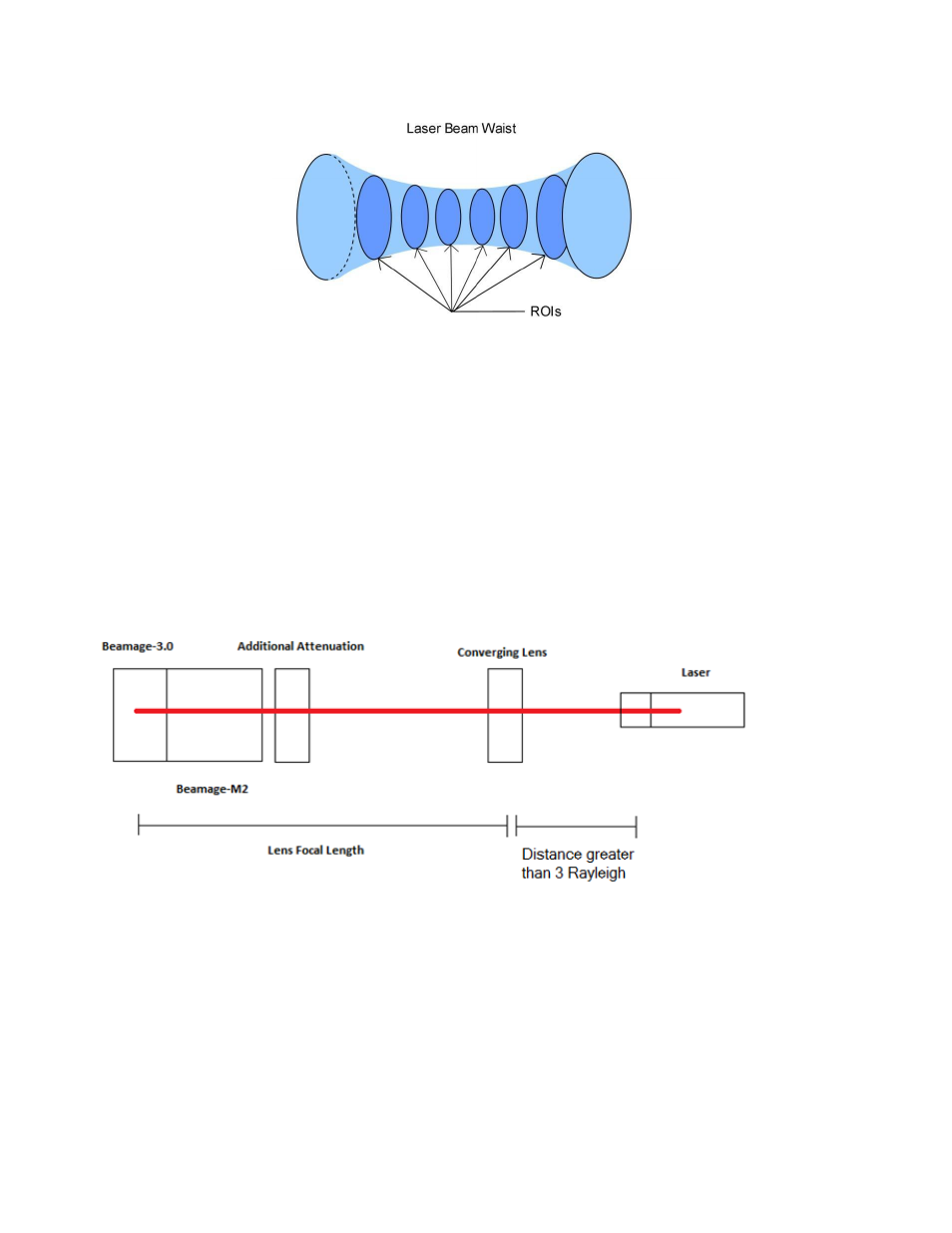
Figure 2-3 Time Delayed Spatial Slices (ROIs)
Three methods can be used to measure the M
2
factor. The first two methods consist of using only one Beamage-
3.0 camera and one Beamage-M2 module. The third method uses two Beamage-3.0 cameras and one Beamage-
M2 module.
3.
How to Use It
3.1. “Moving Stage” Calibration Mode Mechanical Setup
The first method consists of the simplest optical setup. The Beamage-M2 module must be moved by a known
distance to calibrate the measurement. This method, although simple, has the highest uncertainty.
3.1.1. Standalone Laser
Figure 3-1 Moving stage calibration camera setup with a Standalone Laser
This section will guide you through setting up the necessary components for the M
2
factor measurement with a
single camera and a standalone laser. The use of an optical table or breadboard is recommended to align the
optical elements.
1- Fix the Beamage-M2 module on the optical breadboard using a stand. It is also recommended to use a
short millimetric moving stage to help you move the camera back and forth along the propagation axis.
In a subsequent section, this will help you to calibrate the device accurately.