Calibration – Gentec-EO Beamage-M2 User Manual
Page 15
Beamage-M
2
User Manual Revision 2.0
15
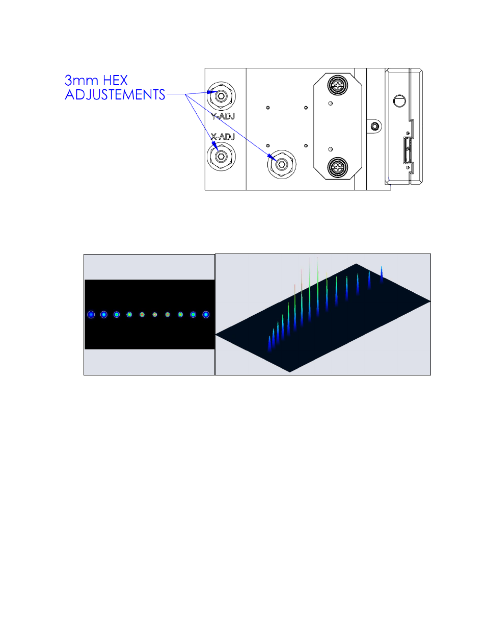
Figure 3-2 Internal Adjustment Screws of the Beamage-M2 Module
4- The system is correctly adjusted once you see a profile similar to the figure shown below. A narrow and
tall spot should be surrounded by smaller and larger spots.
Figure 3-3 Spots Seen With a Correctly Aligned Setup
5- For ISO compliant calculations, at least 10 spots should be detected. Approximately half of the spots
should be distributed on one Rayleigh length around the beam waist and the other half should be
distributed three Rayleigh lengths around the beam waist.
3.1.3. Calibration
Now that your setup is ready, it is time to calibrate it and to make your first M
2
measurement.
1- If it is not already done, run the PC-Beamage-3.0 software.
2- Before working in the M
2
mode, the steps listed below must be followed:
2.1- The active area should be at full resolution (2048 X 1088 pixels)
2.2- There should be no pixel addressing (set to ‘’none’’)
2.3- A background subtraction should be performed
3- Click the M2 mode button in top ribbon and choose Moving Stage Calibration Mode.