FEC AFC1500 User Manual
Page 80
Chapter 4: System Setup and Wiring
Page 4-36
1
5
8
4
1
2
3
4
5
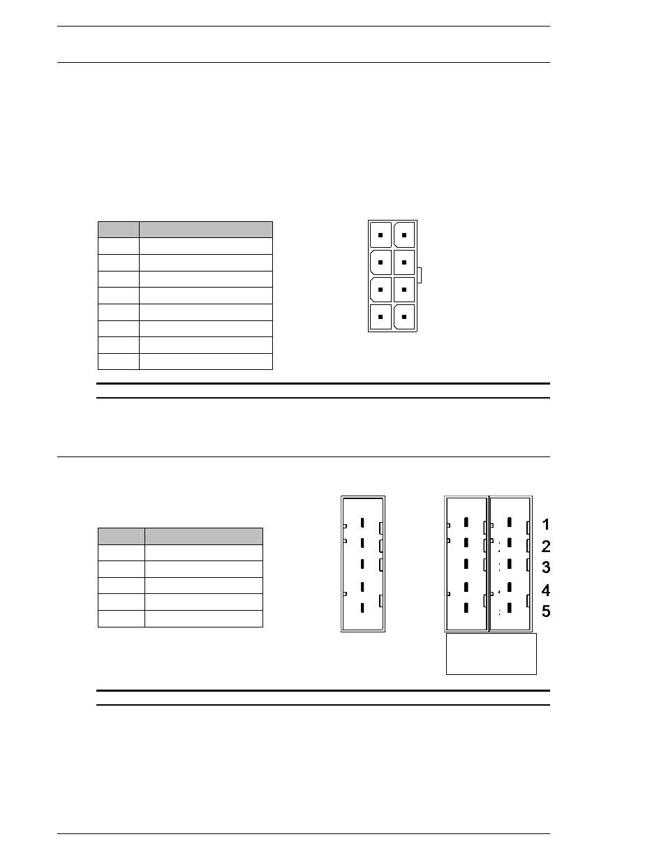
4.11.5 Preamplifier connector.
The preamplifier connector links the Controller to the tool torque transducer in order to per-
form the following functions:
a) Read the torque voltage values from the preamplifier.
b) Test the preamplifier condition by generating a voltage signal for full scale torque
by the CALIBRATION function.
c) Test the preamplifier ZERO level by the ZERO LEVEL CHECK function.
d) Read and Write the EEPROM memory located in the preamplifier. It stores the
Calibration values of the tool, factory tool data and diagnostic information.
PIN
DESCRIPTION
1
SCL -SIGNAL CLOCK
2
SDA -SIGNAL DATA
3
CAL -CALIBRATION
4
TORQUE INPUT
5
FRAME GROUND
6
GROUND
7
-12VDC
8
+12VDC
FIG. 4-11-1: Preamplifier connector.
Mating Connector: Molex #39-01-2085 Pin # 39-00-0047
4.11.6 Motor connector
The Motor connector provides control power to the motor.
PIN
DESCRIPTION
1
FRAME GROUND
2
NOT USED
3
W PHASE
4
V PHASE
5
U PHASE
FIG. 4.11.2: Motor connector.
Standard Mating Connector: AMP #1-178288-5 Pin #1-175218-3
SAN3-120WM ONLY - Mating Connector: AMP #1-178289-5 Pin #1-175218-3
SAN3-120WM
ONLY