7 signal timing chart, Page 4-26 – FEC AFC1500 User Manual
Page 70
Chapter 4: System Setup and Wiring
Page 4-26
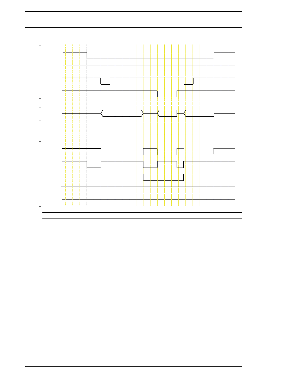
4.7.7 Signal Timing Chart
A. Basic Control Signals
FIG. 4-7-7a Basic Control Signals
{ Because the RESET input clears all fastening data, discrete outputs, and communication buffers, it
should be activated only to clear a System Abnormal or to perform a required Zero Check. The Sys-
tem will automatically reset with each fastening, and a manual RESET activation between cycles
could result in data loss. The RESET signal requires a pulse of 200~500 milliseconds.
{ The STOP input is Normally Closed, and must be enabled for normal operation. When STOP is
disabled, all operations cease and all inputs and outputs become inactive.
{ Once set on, ACCEPT and REJECT signals will latch on until the start of the next cycle.
{ The START signal will not operate during RESET, REVERSE, or ABNORMAL signal activation.
The START signal requires a pulse of 200~500 milliseconds for the AUTO START mode. If the sys-
tem is set-up in DEADMAN mode (Used mainly in handheld applications), this signal has to stay on
during the complete fastening cycle. If the signal is prematurely disabled before the end of cycle, the
spindle will immediately stop.
{ When the ABNORMAL signal is active, normal operation will cease. The Abnormal problem must
be cleared and a RESET must be input to clear the Abnormal output and begin normal operation.
{ REJECT, ACCEPT, ABNORMAL, READY, and BUSY output signals must be interlocked with
BANK 1 and activated only when BANK 1 is selected.
ABNORMAL
PIN 20
ON
OFF
OFF
ACCEPT
PIN 21
REJECT
PIN 22
PIN 12
PIN 13
READY
BUSY
ON
OFF
OFF
PIN 4
START
PIN 2
PIN 1
RESET
OFF
ON
OFF
OFF
ON
STOP
FASTENING
OFF
ON
OFF
PIN 3
REVERSE
ON
OFF
OFF
ON