FEC AFC1500 User Manual
Page 130
Chapter 7: System Operations
Page 7-16
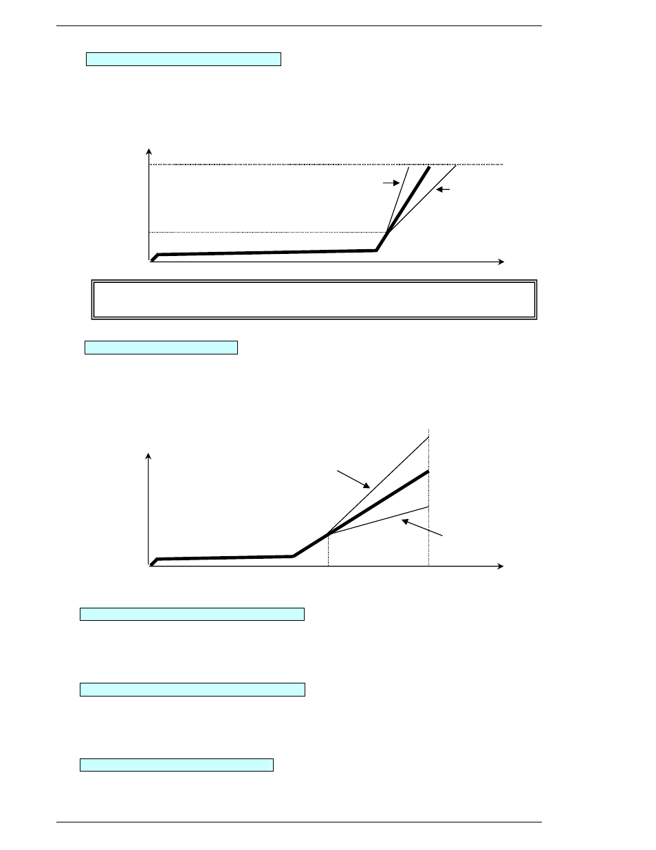
Data No.18 CROS Torque [Nm, Kgm...]
Setting range: 0 ~ [10: Calibration torque] × 1.0
2nd stop / synchronization point for multiple step fastening operations.
End point for 2nd torque rate calculation. [1E: 2
nd
Rate Start Torque is beginning]
Start point for 3
rd
Torque Rate calculation. [Fastening End is the stop point]
Data No.24 CROS Angle [deg] (NOT USED as standard function)
Setting range: 0 ~ 9999
2nd stop / synchronization point for multiple step fastening operations.
End point for 2nd torque rate calculation. [1E: 2
nd
Rate Start Torque or 26: 2
nd
Rate Start Angle
is the beginning]
Start point for 3
rd
Torque Rate calculation. [Fastening End is the stop point]
Data No.19 Torque Inhibit Limit [Nm, Kgm...]
Setting range: 0 ~ [10: Calibration torque] × 1.1
Limit for ignoring the Torque value sensed during Fastening start due to inertia. When the ini-
tial Torque exceeds the Torque Inhibit Limit during [61: Torque Inhibit Revolutions] an
ABNORMAL will be generated and fastening will end.
Data No.1A Offset Torque Limit [Nm, Kgm...]
Setting range: 0 ~ [10: Calibration torque] × 1.1
Maximum value that is acceptable as sensed during an offset check. Offset checking provides
verification that there is not an excess load on the Spindle output drive and provides a refer-
ence value that can be used as a compensation value if Offset Correction is enabled.
Data No.56 Offset Check Speed [rpm]
Setting range: 1 ~ Tool’s maximum rpm.
Speed used to check Offset Torque value.
Angle
Torque
34 Rate 3 Low Limit
35 Rate 3 High Limit
24 CROS
22 Standard
Torque
Angle
13 Standard
18 CROS
34 Rate 3 Low Limit
35 Rate 3 High Limit
If 3rd
t
Torque Rate monitoring is not required, [18:CROS Torque] should be set the same
or higher than [10: Calibration Torque]