2 component dimensions, 1 san controller unit dimensions – FEC AFC1500 User Manual
Page 47
FEC AFC1500 Operations Manual Chapter 4: System Setup and Wiring (Rev. 6.1: 8/12)
Page 4-3
4.2
Component Dimensions
The specifications for all of the AFC1500 standard system equipment is outlined in this Chap-
ter to aid in determining space, mounting & wiring requirements.
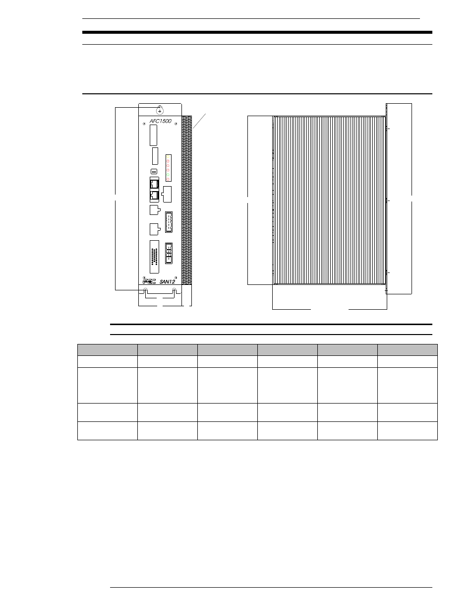
4.2.1 SAN Controller Unit Dimensions
FIG. 4-2-1 SAN Controller unit Dimensions
Unit
A
B
C
D
Weight
SAN2-12
255
60
40
0
1.4 Kg
SAN2-24/40
SAN3-24/40
SAN3-24H
SAN3-60H
255
60
40
14
1.8 Kg
SAN2-80
SAN3-120TW
255
90
60
14.5
3.1 Kg
SAN2-120
SAN3-120WM
255
90
60
33.5
3.6 Kg
Note: Dimensions shown in millimeters.
Screw slot is 5mm width.
The Unit(s) must be mounted with a minimum clearance of 13 mm on each side to allow for
proper heat dissipation. Cable connections on the front of the Units require 100 mm of
clearance.
SAN Units must be located at a minimum 300 mm from any high transient voltage power
source. High transient sources such as relays, AC contactors, AC motor drives, etc. may
cause malfunction of the AFC1500 SAN unit.
All motor cables and I/O cables must be run separate from all high transient voltage sources.
When locating inside an enclosure, avoid mounting at or near the top where internal enclo-
sure heat is most extreme.
HEAT SINK
(SAN40/80 ONLY)
265.00 [10.43]
B
D
C
A
235.00 [9.25]
159.50 [6.28]
MOTOR
AC 200-230V
PLC
T/D
RESOLVER
MON.
ACC.
RUN
485
RS
REJ.
BYPASS
ABN.
BUSY
SV.
SW1
POWER
CON1