Calculating circuit protection – FEC AFC1500 User Manual
Page 58
Chapter 4: System Setup and Wiring
Page 4-14
PIN NUMBER
DESCRIPTION
SAN2-12M~
SAN3-120TM
SAN3-120WM
4
5
200~220 VAC, 50/60Hz, 3-Phase (U) Red
3
4
200~220 VAC, 50/60Hz, 3-Phase (V) White
2
3
200~220 VAC, 50/60Hz, 3-Phase (W) Black
2
Not Connected
1
1
FRAME GROUND
Green
Recommended conductor size = 16 AWG (for all units)
CAUTION: If the equipment is powered on and off repeatedly, internal circuit protec-
tion devices may trip due to high in-rush current overload. It may take up to five
minutes of “off” time to clear the self-protection circuit.
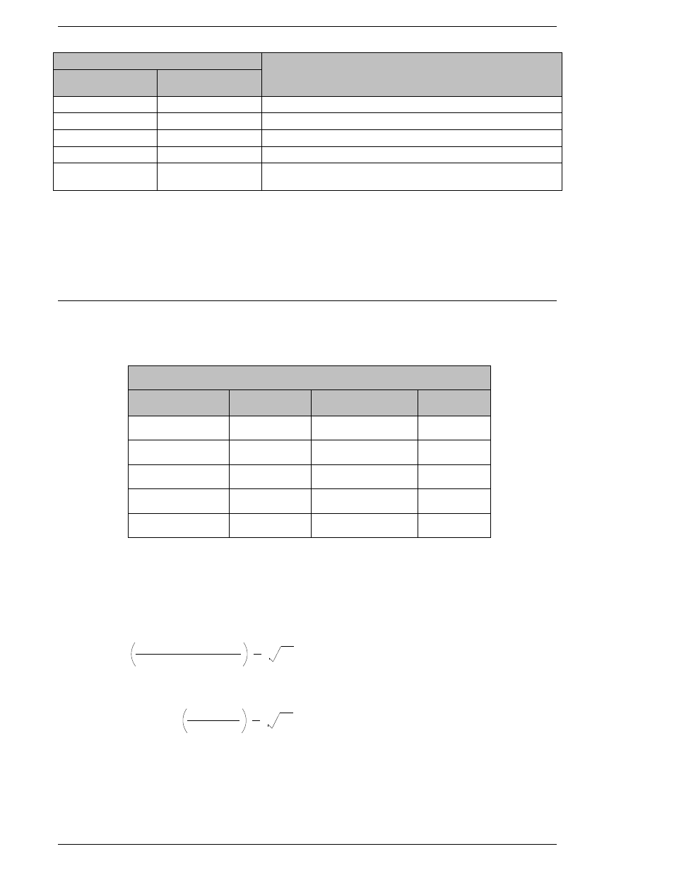
4.6.2. Calculating Circuit Protection
WARNING: Follow Lockout/Tagout and other safety precautions when connecting and/or dis-
connecting cabling, wiring, and equipment.
The chart above shows nominal motor ratings for standard motors, along with the power re-
quirements (KVA) for each spindle. (These already have a safety factor calculated in)
Use the formula below to compute transformer secondary fuse or circuit breaker sizing:
Example:
* Use a fuse or circuit breaker with next available highest rating. Due to the high inrush cur-
rent at power up, it is recommended to use SLOW BLOW type fuses or fuses rated for motor
loads such as Bussman
® FRS/FRN type.
1.5 X
TRANSFORMER (VA)
SECONDARY VOLTAGE
.
.
3
= SECONDARY FUSE SIZE
1.5 X
1000 (VA)
200 VAC
.
.
3
= 4.3 AMP (USE 5 AMP FUSES)*
RATED VALUES FOR CALCULATING CIRCUIT PROTECTION
MOTOR TYPE
MOTOR
WATTAGE
# OF SPINDLES
PER 1 KVA
KVA PER
SPINDLE
RM1
60
10 SPINDLES
.100 KVA
RM2 / RH1
80 / 70
8 SPINDLES
.125 KVA
RM3
200
6 SPINDLES
.166 KVA
RM4 / RH3
1500 / 200
3 SPINDLES
.333 KVA
RM5
3000
1.5 SPINDLES
.666 KVA