9060-zirconia analyser – Teledyne 9060 - Zirconium oxide flue gas oxygen analyzer User Manual
Page 35
9060-Zirconia
Analyser
35
35
3.7b
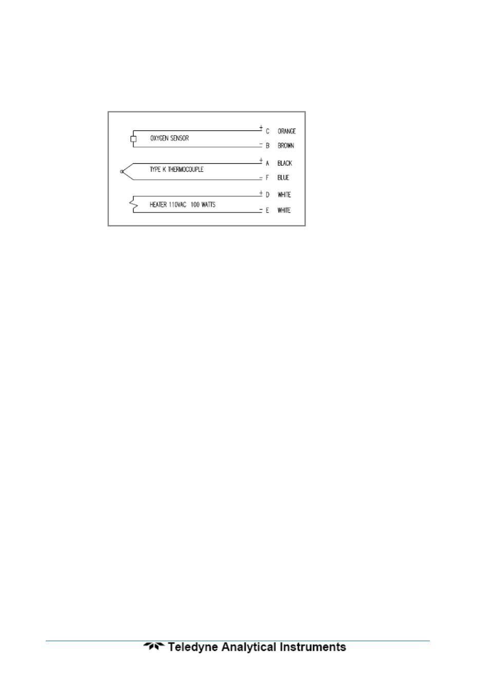
CONNECTING A 1234 SENSOR CABLE
Remove the two screws from the cable gland end of the 1234 sensor. Connect the wiring
as shown below. Be sure to connect an earth to the earth stud. Replace the end plate.
Tighten the cable gland onto the cable.
Connecting a 1234 Sensor Cable
3.8
CONNECTING THE AUXILIARY THERMOCOUPLE (OPTIONAL)
For 1231 heated probes, the auxiliary thermocouple must be a separate TC with the
junction isolated from earth, mounted near to and upstream of the oxygen probe. It can be
either a K or R type thermocouple. It is optional. If the auxiliary temperature is not to be
displayed or transmitted, then an auxiliary TC is not necessary.
3.9
CONNECTING THE OUTPUT CHANNELS
The two 4 to 20 mA DC output channels are capable of driving into a 1000
Ω load.
3.10
CONNECTING THE ALARMS
A common alarm, which should be connected for all installations initiates on alarms
functions described below. Three additional alarm relays are available for selectable
functions as listed in Section 4.2 and 4.3. Each relay has normally closed contacts. The
contacts will open in alarm condition except for the optional horn function that operates
with normally open contacts. Relays are connected as follows:
Relay
Terminal
Numbers
Common Alarm
29 & 30
Alarm 2
31 & 32
Alarm 3
33 & 34
Alarm 4
35 & 36
Common Alarms
All of the following conditions will cause a common alarm -
ADC Calibration Fail
DAC Calibration Fail
Sensor 1 Fail
Sensor 2 Fail*
Heater 1 Fail
Heater 2 Fail*
Sensor 1 TC Open
Sensor 2 TC Open*
Aux. TC Open