Calibration procedure – GF Signet 8850 ProcessPro Conductivity-Resistivity Transmitter User Manual
Page 8
8
8850-3 Conductivity/Resistivity Transmitter
Calibration Procedure
This instrument has been electronically calibrated at the factory.
• Procedure
A
verifi es the accuracy and linearity of the instrument by simulating temperature and conductivity values with precision
(±0.1%) fi xed resistors.
• Procedure B is a wet calibration. This procedure uses the sensor input and NIST traceable test solutions. When done correctly, this
procedure offers the most accurate system calibration.
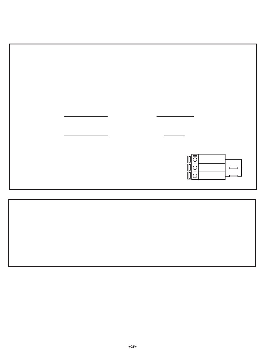
Iso. Gnd
(BLACK)
Temp. IN
(WHITE)
Signal IN
(RED)
13
12
11
Simulation resistor
TC resistor
B) Wet Calibration with NIST Traceable Solutions:
When using NIST traceable standards, review the temperature information provided with the test solution. Prevent contamination of the
test solution. The sensor must be at the temperature specifi ed on the test solution label.
• Remove the sensor from the system. Rinse the sensor in a small amount of test solution.
• Place the sensor into the test solution.
• Place a reference thermometer into the same solution.
• Allow
suffi cient time for the temperature to stabilize.
• Set Temp:
Adjust the temperature value based on the reference thermometer. (see Editing Procedure.)
• Set Cond:
Adjust the conductivity value based on the test solution value. (see Editing Procedure.)
• Verify the linearity by placing the sensor into a second test solution of a different value.
• If the instrument does not display the correct value (Temperature ± 0.5 ºC, Conductivity ± 2% of reading), service is required.
A) Accuracy Verifi cation with Precision Resistors (Electronic Calibration):
1. Simulate the Temperature
The temperature input to the 8850 is a PT-1000 thermistor, where 1000 Ohms (
) is equal to 0 ºC and a change of 3.84 equals a
1 ºC change. (1000
= 0 ºC, 1003.84 = 1.0 ºC, 1007.68 = 2.0 ºC...................1096 = 25 ºC)
• Connect a resistor (1000
to 1096 ) between "Temp IN" and "Iso. Gnd" terminals.
• Set Temp;
Adjust the temperature to exact value based on the measured resistance. (see Editing Procedure, Calibrate menu).
• To verify the temperature linearity, connect a second resistor value to the terminals.
• If the instrument does not display the correct value, service is required. ( ± 0.5ºC)
2. Simulate the Conductivity
You may calculate the exact Resistance needed to simulate a specifi c conductivity value , or you may calculate the exact Conductivity
based on a resistor value:
Resistance
= Cell constant e.g.
0.1 Cell
= 5,000
or 5 K
conductivity
(Siemens*)
0.000020
(Siemens*)
Conductivity
=
Sensor cell e.g.
0.1 Cell
= 0.000001 Siemens*
Simulation resistance (Ω)
100,000 (Ω)
or 1μS/cm
(*1 μS = 1 X 10
-6
Siemens or 0.000001 Siemens)
• Connect the conductivity resistor between the "Signal IN " and "Iso Gnd" terminals.
• Set Cond:
Adjust the conductivity value based on the resistor value. (see Editing
Procedure and Calibrate menu).
• Verify the linearity of the instrument by connecting a second resistor of a different value.
• If the instrument does not display the correct value (± 2% of reading), service is required.