GF Signet 8850 ProcessPro Conductivity-Resistivity Transmitter User Manual
Page 2
2
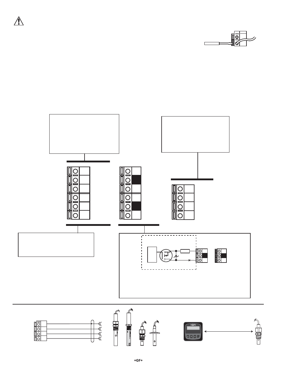
8850-3 Conductivity/Resistivity Transmitter
14
13
12
11
Shield (Sensor Gnd)
Black (Iso Gnd)
White (Temp In)
Red (Signal In)
Signet 28XX-1
Standard and Certified Cells
Terminals
3.1 Sensor Input Connections
≤ 30 m (100 ft)
Signet
Conductivity/Resistivity
Transmitter
ENTER
62.50 uS/cm
25.0 C
Sensr Gnd
(SHIELD)
Iso. Gnd
(BLACK)
Temp. IN
(WHITE)
Signal IN
(RED)
14
13
12
11
Output 2-
Output 2+
Output 1-
Output 1+
10
9
8
7
Loop 2-
Loop 2+
System Pwr
Loop -
System Pwr
Loop +
AUX
Power -
AUX
Power +
6
5
4
3
2
1
3. Electrical
Connections
Caution:
Failure to fully open terminal jaws before removing wire may permanently damage instrument.
Wiring Procedure
1. Remove 0.5 to 0.625 in. (13 to16 mm) of insulation from wire end.
2. Press the orange terminal lever downward with a small screwdriver to open terminal jaws.
3. Insert exposed (non-insulated) wire end in terminal hole until it bottoms out.
4. Release orange terminal lever to secure wire in place. Gently pull on each wire to ensure a good connection.
Wiring Removal Procedure
1. Press the orange terminal lever downward with a small screwdriver to open terminal jaws.
2. When fully open, remove wire from terminal.
Wiring Tips:
• Do not route sensor cable in conduit containing AC power wiring. Electrical noise may interfere with sensor signal.
• Routing sensor cable in grounded metal conduit will help prevent electrical noise and mechanical damage.
• Seal cable entry points to prevent moisture damage.
• Only one wire should be inserted into a terminal. Splice double wires outside the terminal.
2
1
Terminals 7-10: Open-collector Outputs
• Two transistor outputs, programmable as:
• High or Low setpoint with adjustable hysteresis
• Proportional Pulse (to 400 pulses per minute maximum)
• May be disabled (Off) if not used
Terminals 3–6: Loop Power
12 to 24 VDC ±10% system power
and current loop output.
Max. loop impedance:
50
max. @ 12 V
325
max. @ 18 V
600
max. @ 24 V
Terminals 11–14: Sensor Input
11 is conductivity input
12 is temperature input
13 is the isolated signal ground
14 is the sensor earth ground
Terminals 1–2: Auxiliary power
Provides DC power to measurement
circuit. Required for all 8850 systems
1
Internal open-collector
output circuit
Outputs
Isolation
15 Ω
S
D
2
_
+