Warning, Important, Hardware con¿ guration – GF Signet 2551 Magmeter Flow Sensor - Blind User Manual
Page 4
4
2551 Magmeter
Important:
• The directional arrow on the sensor body MUST be pointed DOWNSTREAM for correct operation.
(Digital (S
3
L) and 4 to 20 mA will not work if À ow is against direction of arrow).
• The FLOW arrow decal can be placed directly on the pipe to identify the direction of À ow.
• Use a cable gland or a liquid tight connector to seal the cable ports from water intrusion.
• The yellow housing may be reversed to align the conduit ports as required.
• If the Magmeter is installed on a vertical pipe, the conduit ports should be turned to point downward.
This will prevent condensation from being channeled into the enclosure.
• Use plumber's tape or a suitable sealant on cable ports.
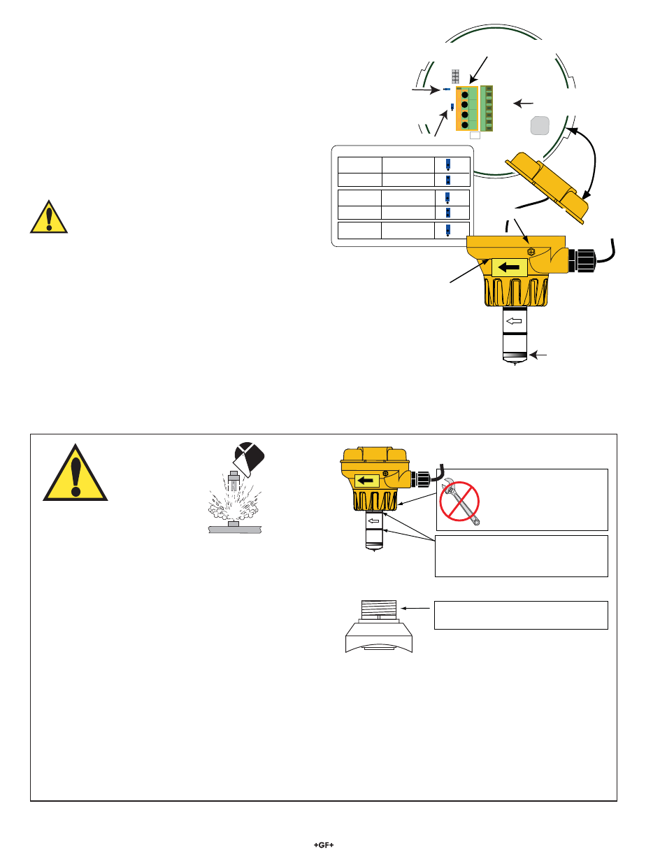
5. Hardware
Con¿ guration
Whether using the 2551-XX-11 (with frequency or Digital (S
3
L)
output) or the 2551-XX-12 (with 4 to 20 mA output), the wiring
terminals located on the inside of the yellow cover are identical.
All of the connections from the Magmeter to external equipment
(PLC, Datalogger, Chart Recorder, Flow meter, etc.) are made at
the large 4-position terminal connector.
When the cover is removed the wiring from the sensor can be
seen connected to the smaller terminal block. These connections
should always remain connected to prevent inadvertent damage
or miswiring.
The terminals on the 2551 Magmeter are designed for conductors
from 16 AWG to 22 AWG.
WARNING!
If the second conduit port is used, carefully drill the
opening. (The plastic is too strong to be punched out.)
• Secure the Magmeter in a vise to prevent damage or injury.
• The plastic inside the port is very thin. Do not allow the drill to
penetrate too deeply and damage the Magmeter wiring.
1
2
3
4
JP2
White
Yellow
Red
Black
Brown
Blue
Not used
The factory connects
the sensor cable to the termin
inside the yellow cover.
This blue jumper selects
frequency output or
S
3
L serial data output
in the 3-2551-XX-11
(Not used on 2551-XX-12 models)
The user must connect output cables to
this 4-terminal block.
JP2 is for factory use only.
MAKE NO CONNECTIONS.
Use the yellow decal to mark
the direction of flow on the pipe
Set this blue jumper according to the pipe size.
External Earth Ground Terminal
Sensor Type
Pipe Size
Jumper Position
2551-P0/T0/V0
½ in. to 2½ in.
DN15
to
DN65
2551-P0/T0/V0
3 in. to 4 in.
DN80
to
DN100
2551-P1/T1/V1
5 in. to 6 in.
DN125
to
DN150
2551-P1/T1/V1
8
in.
DN200
2551-P2/T2/V2
10 in. to 12 in.
DN250
to
DN300
Sensor grounding ring
3-9000.392-1
Liquid tight connec
(one supplied)
Flow
FAILURE TO FOLLOW THESE INSTRUCTIONS MAY RESULT IN
THE SENSOR BEING EJECTED FROM THE PIPE!
• DO NOT USE ANY TOOLS ON THE RETAINING CAP.
HAND TIGHTEN ONLY.
• LUBRICATE O-RINGS WITH A NON-PETROLEUM BASED,
VISCOUS LUBR ICANT (GREASE) COMPATIBLE WITH
THE SYSTEM.
• DO NOT USE THREAD SEALANT OR LUBRICANTS ON THE
RETAINING CAP OR ON THE PLASTIC FITTING THREADS.
• IF LEAKING IS OBSERVED FROM THE RETAINING CAP, IT INDICATES DEFECTIVE OR WORN O-RINGS ON THE SENSOR.
DO NOT ATTEMPT TO CORRECT BY FURTHER TIGHTENING.
WARNING!
DO NOT USE thread sealant or
lubricants on the fitting threads.
Do not use any tools to
tighten the yellow retaining
cap. DO NOT USE thread
sealant or lubricants on
retaining cap!
Lubricate O-rings with a viscous
non-petroleum based lubricant
(grease) compatible with the system.
Flow
CHEMICAL COMPATIBILITY WARNING
The retaining nuts of Magmeters are not designed for prolonged contact with aggressive substances. Strong acids, caustic substances
and solvents or their vapor may lead to failure of the retaining nut, ejection of the sensor and loss of the process À uid with possibly
serious consequences, such as damage to equipment and serious personal injury. Retaining nuts that may have been in contact with
such substances, e.g. due to leakage or spilling, must be replaced.