Speci¿ cations – GF Signet 2551 Magmeter Flow Sensor - Blind User Manual
Page 2
2
2551 Magmeter
2. Speci¿ cations
10
20
30
40
50
60
70
80
90
100
110
120
130
140
150
160
170
180
.7
1.4
2.1
2.8
3.4
4.1
4.8
5.5
6.2
6.9
7.6
8.3
9.0
9.7
10.3
11.0
11.7
12.4
(bar)
(psi)
0
-20
0
20
40
60
80
100
120
°F
°C
-4
32
68
104
140
176
212
248
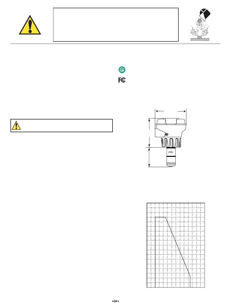
Dimensions
Operating Temperature/Pressure
General
Pipe size range:
DN15 to DN 900 (0.5 in. to 36 in.)
Flow Range
• Minimum:
0.05 m/s (0.15 ft/s)
• Maximum:
10 m/s (33 ft/s)
Linearity:
± 1% reading plus 0.01m/s (0.033 ft/s)
Repeatability:
± 0.5% of reading @ 25 °C (77 °F)
Min. Conductivity:
20 S/cm
Wetted Materials:
• Sensor body and Electrodes and Grounding ring:
• -P0, -P1, -P2:
Polypropylene and 316L SS
• -T0, -T1, -T2:
PVDF and Titanium
• -V0, -V1,-V2:
PVDF and Hastelloy-C
• O-rings:
FPM (standard); EPDM, FFPM (optional)
The user is responsible for determining the chemical
suitability of these materials for a speci¿ c application.
Electrical
Power Requirements
• 4 to 20 mA:
21.6 to 26.4 VDC, 22.1 mA max.
• Frequency:
5 to 26.4 VDC, 15 mA max.
• Digital (S
3
L):
5 to 6.5 VDC, 15 mA max.
Reverse polarity and short circuit protected
Current output (4 to 20 mA):
• Loop Accuracy:
32 A max. error (25 °C @ 24 VDC)
• Isolation:
Low voltage < 48 VAC/DC from electrodes
and auxilary power
• Max cable:
300 m (1000 ft.)
• Error condition:
22.1 mA
• Max. Loop
Resistance: 300
ȍ
• Compatible with PLC, PC or similar equipment
Frequency output:
• Max. Pull-up
Voltage: 30
VDC
• Compatible with Signet 5600, 8900, 9900
Digital (S
3
L) Output:
• Serial ASCII, TTL level 9600 bps
• Compatible with Signet 8900, 9900
Environmental Requirements
• Case:
PBT
• Display:
Polyamide
Storage Temperature: -20 to 70 °C (-4 to 158 °F)
Relative Humidity:
0 to 95% (non-condensing)
Operating Temperature:
• Ambient:
-10 to 70 °C (14 to 158 °F)
• Media:
0 to 85 °C (32 to 185 °F)
Max. operating pressure:
• 10.3 bar @ 25 °C (150 psi @ 77 °F)
• 1.4 bar @ 85 °C (20 psi @ 185 °F)
Standards and Approvals
CE, UL
NEMA 4X / IP65 Enclosure (with cap installed)
94 mm
(3.7 in.)
79.25 mm
(3.12 in.)
-X0
-X1
-X2
Pipe Range:
1/2 to 4 in. -X0 = 58 mm (2.3 in.)
5 to 8 in.
-X1 = 91 mm (3.6 in.)
10 to 36 in. -X2 = 167 mm (6.6 in.)
X = Sensor Body P, T, or V
China RoHS
For more information go to www.gfsignet.com
SAFETY INSTRUCTIONS
1. Depressurize and vent system prior to installation or removal.
2. Con¿ rm chemical compatibility before use.
3. Do not exceed maximum temperature/pressure speci¿ cations.
4. Wear safety goggles or face shield during installation/service.
5. Do not alter product construction.
6. Disconnect power before attempting any service or wiring.
Declaration of Conformity according to FCC Part 15
This device complies with Part 15 of the FCC rules.
Operation is subject to the following two conditions:
(1) This device may not cause harmful interference, and,
(2) This device must accept any interference received,
including interference that may cause undesired operation.