English, Refer to "fig. 42" and "fig. 43, T 250 ma – Burkert Type 8035 User Manual
Page 48: 20ma input at external instrument
48
Wiring
Type 8025/8035 /
The wiring of the pulse output of a wall-mounted version with relays
is the same as the wiring of a version without relays.
→
Refer to "Fig. 42" and "Fig. 43".
Supply
12..36Vdc
NPN SENSOR
1 PULSE INPUT
2 -
3 +
4 NC
SUPPLY
1
2
3
4 PE
3A/230VAC
REL1
REL2
FLOW SENSOR
FLOW SENSOR
COIL
NPN
CURRENT
SOURCE SINK
COIL SENSOR
1
2
3 NC
4 NC
L+
L-
PE
P-
P+
NC
L+
L-
PE
P-
P+
Iout
PULSE
OUTPUT
Without
With
Relays
230V
T 250 mA
L N
230V
5 6 7 8 9 10
L N
230V
{
+
-
PE
4-20mA input at
external instrument
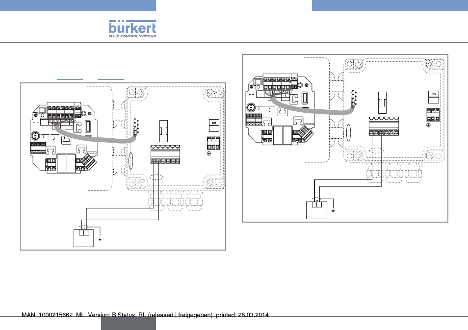
Fig. 45: Wiring in sinking mode of the current output of a wall-
mounted version, 115 -230 V AC, with relays
Supply
12..36Vdc
NPN SENSOR
1 PULSE INPUT
2 -
3 +
4 NC
SUPPLY
1
2
3
4 PE
3A/230VAC
REL1
REL2
FLOW SENSOR
FLOW SENSOR
COIL
NPN
CURRENT
SOURCE SINK
COIL SENSOR
1
2
3 NC
4 NC
L+
L-
PE
P-
P+
NC
L+
L-
PE
P-
P+
Iout
PULSE
OUTPUT
Without
With
Relays
230V
T 250 mA
L N
230V
5 6 7 8 9 10
L N
230V
{
+
-
PE
4-20mA input at
external instrument
Fig. 46: Wiring in sourcing mode of the current output of a wall-
mounted version, 115 -230 V AC, with relays
English