Burkert Type 8035 User Manual
Page 23
23
Wiring
Type 8025/8035 /
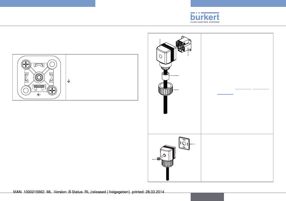
8.2.
Wiring the 8025 compact version
and the 8035 with a 4 pin male
fixed connector
1
2
3
1 : V+ (12-36 V DC)
2 : Positive pulse output
3 : L- ( 0 V DC)
: Negative pulse output
Fig. 14: Pin assignment of the 4 pin male fixed connector
1
2
3
4
→
Unscrew the nut 1 of the cable
gland.
→
Remove the terminal block 3 from
the housing 2.
→
Insert the cable through the nut
[1] then through the gasket [4],
through the cable gland and
finally through the housing [2].
→
Connect the wires on terminal
block [3], see "Fig. 14", "Fig. 16"
and "Fig. 17".
→
Position the terminal block [3] in
steps of 90° then put it back into
the housing [2], pulling gently on
the cable so that the wires do not
clutter the housing.
→
Tighten the nut [1] on the cable
gland.
6
5
→
Place the seal [5] between the
connector and the fixed con-
nector on the device and then
plug the 2508 connector into the
fixed connector.
→
Insert and then tighten the screw
[6] to ensure tightness and
correct electrical contact.
Fig. 15: Assembling the female connector type 2508 (supplied)
English