Burkert Type 8035 User Manual
Page 42
42
Wiring
Type 8025/8035 /
→
Insert the cable clips: See "Fig. 21".
The wiring of the current output and the wiring of the pulse output of
the panel or wall-mounted transmitter, 12-36 V DC, without relays,
are the same as for a compact flowmeter, 12-36 V DC, with relays,
with cable glands.
→
Wire the current output according to "Fig. 27" of chap. "8.4.4".
→
Wire the pulse output according to "Fig. 28" of chap. "8.4.4".
8.7.
Wiring the 8025, wall-mounted
version, 115/230 V Ac, with or
without relays
8.7.1. Wiring instructions for a wall-
mounted version
Seal the unused cable gland using the stopper gasket sup-
plied to make sure the device is tight.
→
Unscrew the nut of the cable gland.
→
Remove the transparent disc inside the cable gland.
→
Insert the stopper gasket.
→
Screw the nut back.
→
Connect the flow sensor to the remote transmitter according to
chap. "8.5".
→
Configure the selectors on the electronic board: see chap. "8.3".
→
Loosen the nuts of the cable glands.
→
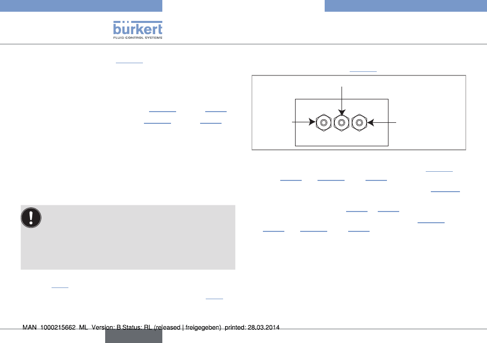
Insert each cable through a nut then through the cable gland, using
the cable glands as shown in "Fig. 39".
Flow sensor
cable
Cables of the outputs
Power supply cable,
12-36 V DC or
115/230 V AC
Fig. 39: Using the cable glands
→
→
For the versions with relays, insert the cable clip. See "Fig. 21".
→
Depending on the version (with or without relays), wire the
device according to chap. "8.7.2" or "8.7.3".
→
→
Letting the housing stay completely open, secure the power
supply cable, the flow sensor connection cable and, depending
on the version, the relay connection cables, with the cable clips.
→
Tighten the cable glands making sure the cable in the housing is
long enough to allow complete opening of the housing.
→
Close the cover.
→
Tighten the 4 screws.
→
Put the blanking strips on the housing.
English