English – Burkert Type 8035 User Manual
Page 24
24
Wiring
Type 8025/8035 /
→
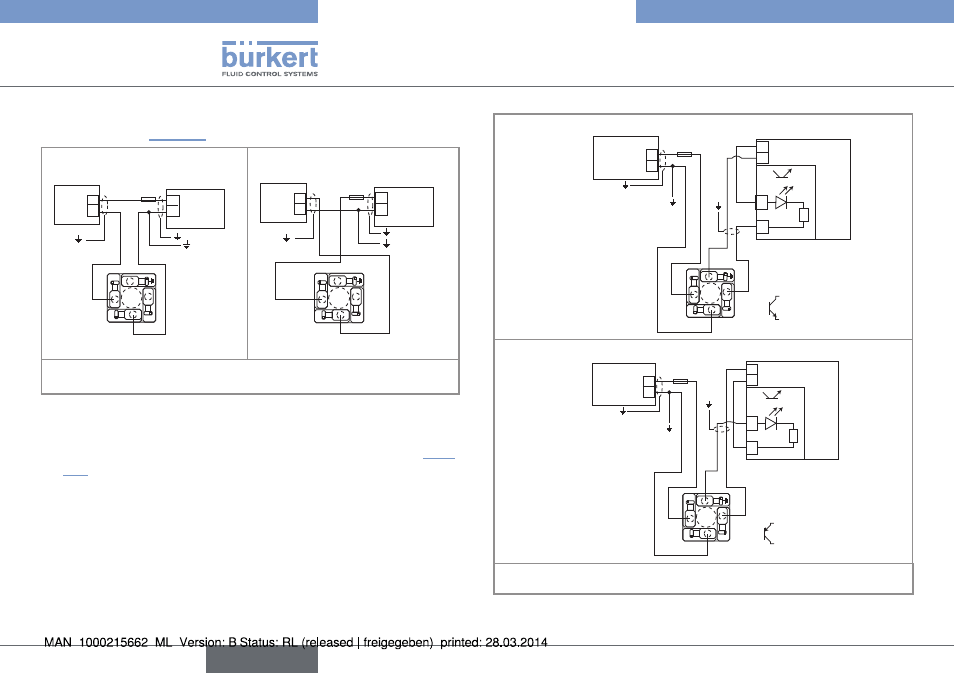
Wire the electrical supply and the current output using one of the
wiring plan of "Fig. 16".
300 mA
+
-
12-36 V DC
+
-
(*)
1
3
2
L+
L-
P
ower supply
4-20mA input at external
instrument
4-20mA input at external
instrument
300 mA
+
-
12-36 V DC
+
-
(*)
1
3
2
L+
L-
P
ower supply
(*) If direct earthing is not possible, insert a 100 nF / 50 V condensator between the
negative terminal of the voltage supply and the earth.
Fig. 16: Possible wiring of the current output of a compact version
with male fixed connector
→
Wire the transistor output using one of the wiring plans of "Fig.
17".
Wiring of the pulse output in npn mode
300 mA
+
-
12-36 V DC
(*)
+
-
1
3
2
L+
L-
P+
P-
8025:
NPN
P+
P-
+
- 5-36 V DC
Power supply
PLC
Wiring of the pulse output in pnp mode
+
-
300 mA
+
-
12-36 V DC
(*)
1
3
2
L+
L-
P+
P-
8025:
PNP
P+
P-
+
- 5-36 V DC
Power supply
PLC
(*) If direct earthing is not possible, insert a 100 nF / 50 V condensator between the
negative terminal of the voltage supply and the earth.
Fig. 17: Wiring of the pulse output in NPN or PNP mode, of a compact
version with male fixed connector
English