English, Connect the relays according to chap. "8.4.2 – Burkert Type 8035 User Manual
Page 38
38
Wiring
Type 8025/8035 /
Supply
12..36Vdc
FLOW SENSOR
COIL
NPN
SOURCE SINK
L+
L-
PE
P-
P+
NC
L+
L-
PE
P-
P+
Iout
PULSE
OUTPUT
Without
With
Relays
N
PE
L
230V
T 125 mA
{
5-36 V DC
+
-
8025:
NPN
P+
P-
+
-
PE
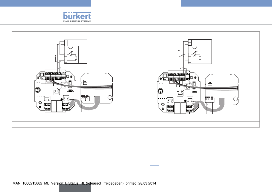
Wiring of the pulse output in npn mode
115/230 V AC power supply
PLC
Supply
12..36Vdc
FLOW SENSOR
COIL
NPN
SOURCE SINK
L+
L-
PE
P-
P+
NC
L+
L-
PE
P-
P+
Iout
PULSE
OUTPUT
Without
With
Relays
N
PE
L
230V
T 125 mA
{
8025:
PNP
P+
P-
+
-
+
-
5-36 V DC
PE
115/230 V AC power supply
PLC
Wiring of the pulse output in pnp mode
(*) If direct earthing is not possible, insert a 100 nF / 50 V condensator between the negative terminal of the voltage supply and the earth.
Fig. 35: Wiring, in NPN or PNP mode, of the pulse output of a 115/230 V AC compact version, with relays, with cable glands
→
Connect the relays according to chap. "8.4.2".
8.5.
connecting the flow sensor to the 8025 transmitter, panel-mounted version
or wall-mounted version
→
Configure the FLOW SENSOR selector on the electronic board (see chap. "8.3").
→
Connect the remote flow sensor to the FLOW SENSOR terminal block of the electronic board by respecting the pin assignment
depending on the output type of the remote sensor, either sinus (COIL) or pulse output (NPN).
English