English, 32 1 a – Burkert Type 8035 User Manual
Page 40
40
Wiring
Type 8025/8035 /
Supply
12..36Vdc
FLOW SENSOR
COIL
NPN
L+
L-
PE
P-
P+
NC
L+
L-
PE
P-
P+
Iout
PULSE
OUTPUT
Without
With
Relays
NPN SENSOR
1 PULSE INPUT
2 -
3 +
4 NC
SUPPLY
1
2
3
4 PE
REL1
REL2
COIL SENSOR
1
2
3 NC
4 NC
3
2
1
A
PE
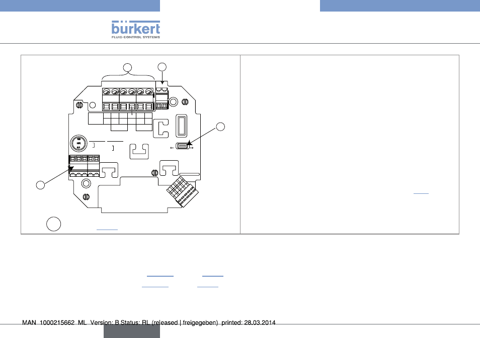
Switch A : see chap. "8.3.1"
terminal block 1
NC: not connected
L+: positive power supply
L-: negative power supply
PE: wiring of the PE between the main board and the protection
board
P-: negative pulse output
P+: positive pulse output
terminal block 2 pe
Wiring of the cable shields
connector 3: connection of the flow sensor, see chap. "8.5"
Fig. 37: Terminal assignment of a panel-mounted or wall-mounted version, 12-36 V DC, without relays
The wiring of the current output and the wiring of the pulse output of the panel or wall-mounted transmitter, 12-36 V DC, without relays, are
the same as for a compact flowmeter, 12-36 V DC, without relays, with cable glands.
→
Wire the current output according to "Fig. 24" of chap. "8.4.3".
→
Wire the pulse output according to "Fig. 25" of chap. "8.4.3".
English