Burkert Type 8035 User Manual
Page 16
16
Installation
Type 8025/8035 /
→
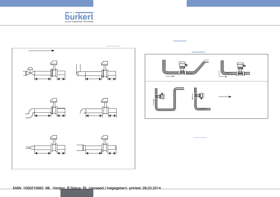
Install the device on the pipe in such a way that the upstream and
downstream distances are respected according to the design of
the pipes, refer to standard EN ISO 5167-1 and "Fig. 4":
flow direction
50 x DN 5 x DN
40 x DN 5 x DN
25 x DN 5 x DN
20 x DN 5 x DN
18 x DN 5 x DN
15 x DN 5 x DN
With control valve
Pipe with 2 elbows at 90° in 3
dimensions
Pipe with 2 elbows at 90°
Pipe with 1 elbow at 90° or 1
T-piece
With pipe expansion
With pipe reduction
Fig. 4: Upstream and downstream distances depending on the
design of the pipes
→
Ensure that the pipe is always filled in the section around the
device (see "Fig. 5").
→
When mounting vertically ensure that the flow direction is in an
upward direction (see "Fig. 5").
Horizontal mounting
Correct
Incorrect
Vertical mounting
Correct
Incorrect
flow direction
Fig. 5: Filling of the pipe
→
Prevent the formation of air bubbles in the pipe in the section
around the device (see "Fig. 6").
English