Connecting the nextage 16, 1 description, 1 rear panel – Analog Way SmartMatriX Ultra User Manual
Page 23: Connecting the smartmatrix ultra
23
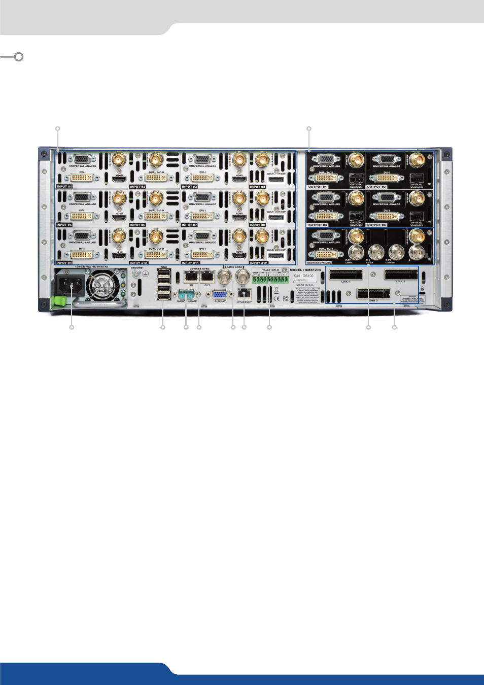
5.1.1 Rear panel
1.
Removal Power supply:
100-240 VAC; 8A; 50/60Hz; 285W; internal, autoswitchable.
2.
Inputs #1 to #12:
- 6 x HDMI
- 9 x DVI-I (Dual link available on Inputs 2, 6 & 10)
- 3 x DisplayPort (Dual link available on Inputs 4, 8 & 12)
- 12 x 3G/HD/SD-SDI
- 12 x Universal Analog (6 x HD15 & 6 x DVI-A)
3. Outputs #1 to #4:
- 4 x Universal Analog (HD15 & DVI-A)
- 4 x DVI-I (DVI Dual-Link on outputs #1 & #3)
- 4 x Video Optical SFP module cage
- 4 x 3G/HD/SD-SDI
4.
Monitoring Preview output:
- 1 x Universal Analog (HD15 & DVI-A)
- 1 x DVI-I
- 2 x SD/HD/3G SDI
- 1 x RGBs/RGsB/RGB/YPrBr/YC/comp Analog output
5.
Tally, GPI-O connector
6.
Ethernet plug
7.
Frame Lock:
Analog Frame Lock plug and specific loop output.
8.
Devices sync.:
Used for effect sync in multi-machine mode.
9.
RS232 port:
Reserved for maintenance.
10.
4 x USB plugs
11. Link cables:
Use the 3 link cables to share inputs/outputs in the additive modularity configuration.
5. CONNECTING THE SMARTMATRIX ULTRA
5.1 Description
5.1.1 Rear panel
2
3
4
1
10
11
9 8
7
5
6