D. three/four wire, E. profibus da/dp, foundation fieldbus, Multiple positioners field wiring split range – Bray 6A Series O&M Manual User Manual
Page 7
All information herein is proprietary and confidential and may not be copied or reproduced without the expressed written consent of BRAY INTERNATIONAL, Inc.
The technical data herein is for general information only. Product suitability should be based solely upon customer’s detailed knowledge and experience with their application.
Series 6A Operation & Maintenance – field Connections
6A O & M : 7
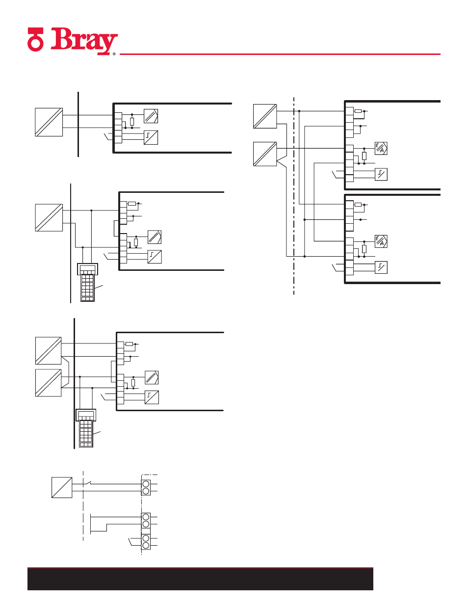
II Hazardous Area (Intrinsically Safe)
A. Two Wire
6
7
8
9
10
#
4 to 20 mA
Positioner
Binary input 1
Intrinsically safe
power source
Non-hazardous area
Hazardous area, Zone 1
EEx
B. and C. Two Wire Connection When Using a 2/3/4 Wire
Device and HART
6
7
8
9
2
3
4
5
10
4 to 20 mA
Positioner
Binary input 1
E
A
Intrinsically safe
power source
Non-Hazardous
area
Hazardous area, Zone 1
EEx
HART Communicator
6A-6DR52**-*E*** only
+
I
#
D. Three/Four Wire
6
7
8
9
2
3
4
5
10
18 to 30 V
Positioner
Binary input 1
E
A
Intrinsically safe
power source
Non-hazardous area
Hazardous area, Zone 1
EEx
EEx
HART Communicator
6A-6DR52**-*E*** only
4 to 20 mA
+
I
+
I
*)
*)
*) Three-wire connection only
#
E. Profibus DA/DP, Foundation Fieldbus
4 ... 20 mA
BE1 = Binary Input
7
8
9
10
+
–
J
6
Input for safety shutdown (activated using coding jumper)
1)
≤ 30 V
≤ 24 V
+
–
BE1 = Binary Input
7
9
10
+
–
6
1)
81
82
Input for safety shutdown (activated using coding jumper)
1)
≤ 24 V
–
BE1 = Binary Input
7
9
10
+
–
6
81
82
HART
modem
PC/Laptop
R 250 W if req.
1)
3
Only required with current sources not conforming to HART
1)
2
3
4
5
+
–
I
l
y
= 4 ... 20 mA
6
7
8
l
W-
l
H+
1) Jumper between 5 and 7 only for three-wire system
2
3
4
5
+
–
J
6
7
8
9
10
4 ... 20 mA
0/4 ... 20 mA
2
3
4
5
+
–
6
7
8
9
10
18 ... 30 V
J
+
–
BE1 = Binary Input
BE1 = Binary Input
1)
Power Supply
Non-Hazardous
Hazardous area, Zone 1
Multiple Positioners Field Wiring
Split Range
6
7
8
9
2
3
4
5
10
6
7
8
9
2
3
4
5
10
+ 18 to 30 V
+ 0/4 to 20 mA
BE1
Entire positioning
range I
y
Auxiliary power
EEx
L+
V
EEx
I
y
I
Positioning range 1
BE1
Positioning range 1
M
M
#
#
Non-hazardous area
Hazardous area, Zone 1
Intrinsically safe power sources
Series connection of 2 positioners, e.g. split range (auxiliary power wired separately), EEx i