Bray 63 N4 Series User Manual
Series 63 n4 operation & maintenance manual
All information herein is proprietary and confidential and may not be copied or reproduced without the expressed written
consent of BRAY INTERNATIONAL, Inc.
The technical data herein is for general information only. Product suitability should be based solely upon customer’s detailed
knowledge and experience with their application.
SERIES 63 N4 Operation & Maintenance Manual
Manual Number OM-63/N4-001
Date: September 2, 2010 Page 1 of 5
Bray Series 63-N4 Installation & Maintenance Instructions
3-Way, or 4-Way, 2 Position Single or Dual Solenoid Valves
For NAMUR Actuators – ¼ NPT Supply & ¼ NPT Exhaust Connections
Air or Inert Gas Service – Anodized Aluminum Construction
Service Notice:
• The Series 63-N4 is not repairable. When
any performance problems are detected
during routine inspection, replace valve
immediately.
• For S63-N4/N7 Solenoids, see O&M In-
structions for information on: Wiring,
Solenoid Temperature, Cause of Improper
Operation, and Coil Replacement.
DESCRIPTION
Series 63 valves are 3-way or 4-way, 5 ported 2
position piloted spool type single or dual sole-
noid valves designed for air or inert gas service.
Valves are made of rugged anodized aluminum.
A built-in manual operator allows manual opera-
tion when desired or during an electrical power
outage. Each valve may be used for 3-way (nor-
mally closed) or 4-way operation by using the
appropriate flow plate provided. Flow plates are
marked (3/2) for 3 Ports, 2 Positions (3-way op-
eration) or (5/2) for 5 Ports, 2 Positions (4-way
operation). These valves are supplied with all
necessary hardware for a NAMUR direct mount
installation i.e. flow plates, gaskets, mounting
screws and a locating set screw. See
Flow Selec-
tion And Mounting section.
APPLICATIONS
Typically, the 3-way (3/2) normally closed mode
is used for a single acting (spring return) actuator;
4-way (5/2) mode for a double acting actuator.
Port Markings: 1 = Supply, 2 & 4 = Open/Close
Actuator ports 3 & 5 = Exhaust
OPERATION
NOTE: Minimum operating supply pressure,
differential 30 psi; maximum 150 psi.
Breather Function 3-way (3/2) mode only: Al-
lows for spring side of a spring return actuator to
vent at all times through valve exhaust port 3.
Single Solenoid: This type of operation is used
where automatic return of the valve on electri-
cal power failure or loss of main line pressure
is required.
12
1
3
4
2
3/2
12
1
3
4
5
2
5/2
Quarter
Turn
Actuator
Process
Valve
Solenoid
Pilot
Valve
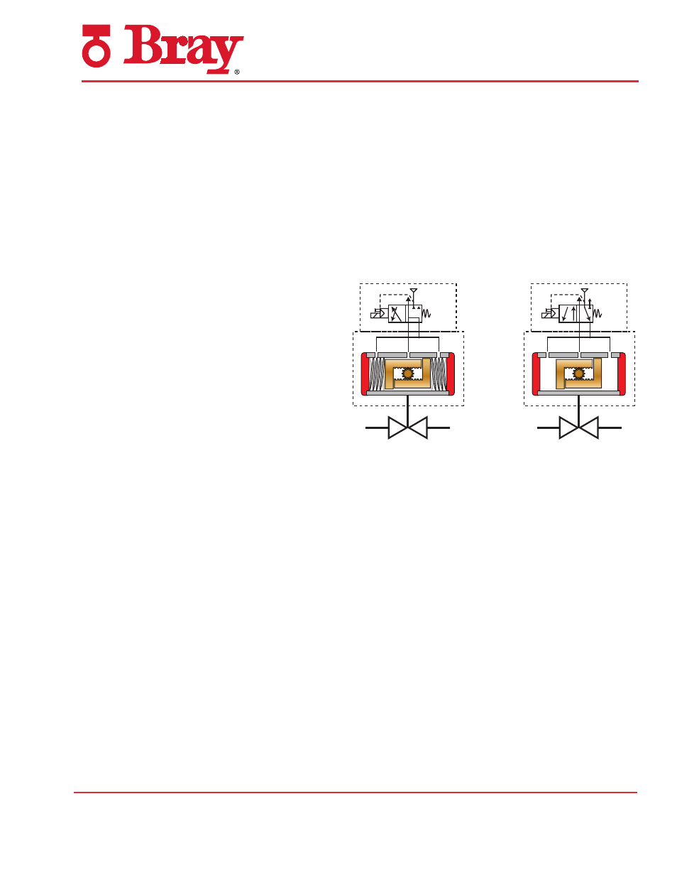
Double-acting
actuator
solenoid spool
valve control
adapted for
5/2 operation
Single-acting
actuator
solenoid spool
valve control
adapted for
3/2 operation