Troubleshooting – Bray 6A Series O&M Manual User Manual
Page 26
All information herein is proprietary and confidential and may not be copied or reproduced without the expressed written consent of BRAY INTERNATIONAL, Inc.
The technical data herein is for general information only. Product suitability should be based solely upon customer’s detailed knowledge and experience with their application.
Series 6A Operation & Maintenance – Troubleshooting
6A O & M : 26
TrOubleShOOTInG
During operation of the positioner, a few important values and parameters are continually monitored. In configuration mode, you can
configure that monitoring so that the fault message output will be activated if, for instance, a limit is exceeded. Information about what
events can activate the fault message output can be found in Figure 16
Fault
See Table #:
In which mode does a fault occur?
Initialization
1
Manual and automatic modes
2, 3, 4, 5
In which environment and under which boundary conditions does a fault occur?
Wet environment (e.g. strong rain or constant condensation)
2
Vibrating (oscillating) control valves
2, 5
Impact or shock loads (e.g. vapor shocks or breakaway valves)
5
Moist (wet) compressed air
2
Dirty (contaminated with solid particles) compressed air
2, 3
When does a fault occur?
Regularly (reproducible)
1, 2, 3, 4
Sporadically (not reproducible)
5
Mostly after a specific operation time
2, 3, 5
In automatic and manual mode, when the fault message output triggers the digital display shows what fault triggered the message.
The two digits on the lower left show the corresponding error code. If multiple triggers occur at the same time, they are displayed one
after the other cyclically. The device status, including all fault messages, can be called up using command “#48” over HART. For other
protocols please refer to their specific guide on
www.bray.com
.
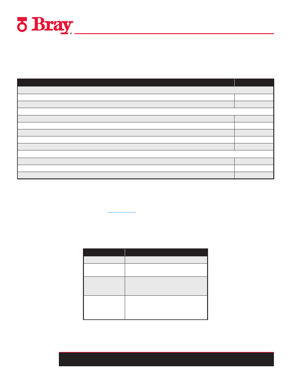
You can use the advance diagnostics parameters to display fault messages in one, two or three stages. The three stage method uses
“traffic light signaling” symbolizing the type of fault occurring. The user will see either a green, yellow, or red wrench on their HMI in
relation to the S6A. Green indicates a need for maintenance, yellow an urgent need for maintenance and red indicates imminent danger
of unit failure or general failure. In addition to the fault message output, alarm outputs 1 and 2 are then used. For this purpose, set the
“XDIAG” parameter as described in Figure 17.
Settings of XDIAG Message due to
OFF
Advanced diagnostics not activated
On 1
Fault message output for threshold 3 fault
messages (one-stage)
On 2
Fault message output for threshold 3 fault
messages and alarm output 2 for threshold
2 fault messages (two-stage)
On 3
Fault message output for threshold 3 fault
messages and alarm output 2 for threshold
2 fault messages and alarm output 1 for
threshold 1 fault messages (three-stage)
When a fault occurs an error code will show up on the lower left hand corner of the screen. Remedial Measures Tables 1-5 respectively,
show possible causes of the fault messages, events which activate the fault message output or alarm outputs, settings of parameters
needed for event monitoring, and remedial measures to cancel a fault message.
Figure 16
-
Fault Messages
Figure 17
XDIAG Parameters