Bray 3HP User Manual
Bray Equipment
Installation and Maintenance Manual
Series 3HP Ball Valves
Date: August 2011 / Page 1 of 2
®
A Subsidiary of BRAY INTERNATIONAL, Inc.
FLOW-TEK, Inc.
Tel: 832.912.2300
© 2011 Flow-Tek, Inc.
8323 N. Eldridge Pkwy #100
Fax: 832.912.2301
Houston, Texas 77041
www.flow-tek.com
INSTALLATION – MAINTENANCE MANUAL
3HP SERIES BALL VALVES
Installation Guide
It is important that the middle port on the valve IS NOT
MOVED otherwise damage will occur to the seats.
1. Before installting the valves, firstly make sure that the
pipework has been cleaned and there is no trace of
debris or loose pieces of metal in the pipe or system.
2. Prepare the threaded pipe for connection to the valve
using either a thread sealant or PTFE tape, ensuring
that there is no surplus tape over the open pipe and
that may become dislodge and be carried through the
pipework system.
3. Taper Threads: Carefully insert the pipe threaded end
into the valve and tighten gently until resistance is felt.
The pressure tight joint can then be made by tighting a
further 1/2 to 1 turn as a guide. This will help prevent
over-thightening and having the risk of damaged
threads and resultant scrapping of components as a
result of poor connection.
4. Parallel Threads: These threads are designed for face
sealing and not bottom face sealing. Using a suitable
bonded washer, insert the threaded pipe into the valve
using a suitable lubricant or sealant if required and
tighten until resistance if felt. The pipe thread can then
be sealed with a further 1/4 turn to ensure that the
face of the thread seals with the washer where used.
Threads can be sealed using a pipe sealant but care
must be taken so as not to ‘bottom’ the thread and
hence cause damage to the lead thread on the male
end which may damage all the threads on removal.
5. When purging the system prior to use, make sure that
the valve is in the fully open position so that any loose
particles that may remain in the system will not mark
the ball or be trapped between the ball and the seats
as this will result in shorter life or leaking of the valve.
6. Finally, the gland seal is designed to be adjustable
and, should the seals settle between manufacturing
and installation, then it is suggested that 1/8 turn
clockwise will ensure no leakage or stop any small
weapage that may occur. This is not a design fault by
and adjustable item.
Operation Guide
This valve is designed to operate with pressure being
applied to the CENTER PORT ONLY. It is not designed to
isolate pressure for either side port.
Side entry style, the handle rotates 90° from open 6 to 3,
to open on the opposite side outlet 6 to 9.
Dismantling Instructions:
1. Remove the valve from the pipeline using a spanner on
the end connector for each side of the pipe.
2. Clean the valve of any residual material.
3. Take out each end connector, holding the spare body
whilst unscrewing each end.
4. Ensure that the handle is in the closed position and
push out the ball and seats in either direction.
5. Remove the handle retaining nut and take both the
handle and the nut off.
19
23
25a
1
2
3
4
6
12
28
25
26
15
14
5
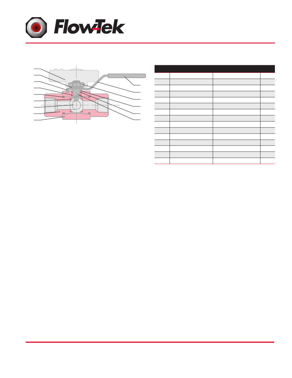
Item Name
Material
Qty.
1
Body
Stainless Steel 316
1
2
End Connector
Stainless Steel 316
2
3
Ball
Stainless Steel 316
1
4
Seat*
PVDF
2
5
Stem
Stainless Steel 316
1
6
Body Seal*
RPTFE
2
12
Thrust Washer*
RPTFE
1
14
Stem Packing*
RPTFE
1
15
Packing Gland
Stainless Steel
1
19
Lock Washer
Stainless Steel
2
23
Stop Pin
Stainless Steel
1
25
Lever Handle
Stainless Steel
1
25a
Pointer Handle
Mazak 3
1
26
Lock Nut
Stainless Steel
1
28
Handle Sleeve
Vinyl
1