Notice – Bray 6A Series O&M Manual User Manual
Page 24
All information herein is proprietary and confidential and may not be copied or reproduced without the expressed written consent of BRAY INTERNATIONAL, Inc.
The technical data herein is for general information only. Product suitability should be based solely upon customer’s detailed knowledge and experience with their application.
Series 6A Operation & Maintenance – Installable Options
6A O & M : 24
NotICe
A pin in the actuating disc bearing is pressed. Align this pin
before it touches the special screw. You must rotate the actuat-
ing disc bearing and the special screw simultaneously so that the
pin is inserted into the special screw.
7. An insulating cover is provided over the SIA unit. Place the
insulating cover to one side under the motherboard seat on
the container wall. The recesses of the insulating cover must
fit in the corresponding webs of the container wall.
8. Place the insulating cover on the SIA unit by bending the
container walls carefully.
9. Engage the motherboard into the four brackets.
10. Tighten the motherboard using the two screws.
11. Reestablish all electrical connections between the mother-
board and the optional modules. Connect the motherboard
and the optional modules to the ribbon cables provided.
Connect the motherboard and the potentiometer to the poten-
tiometer cable.
12. Using both the screws, fasten the module cover provided. Do
not use the standard module cover.
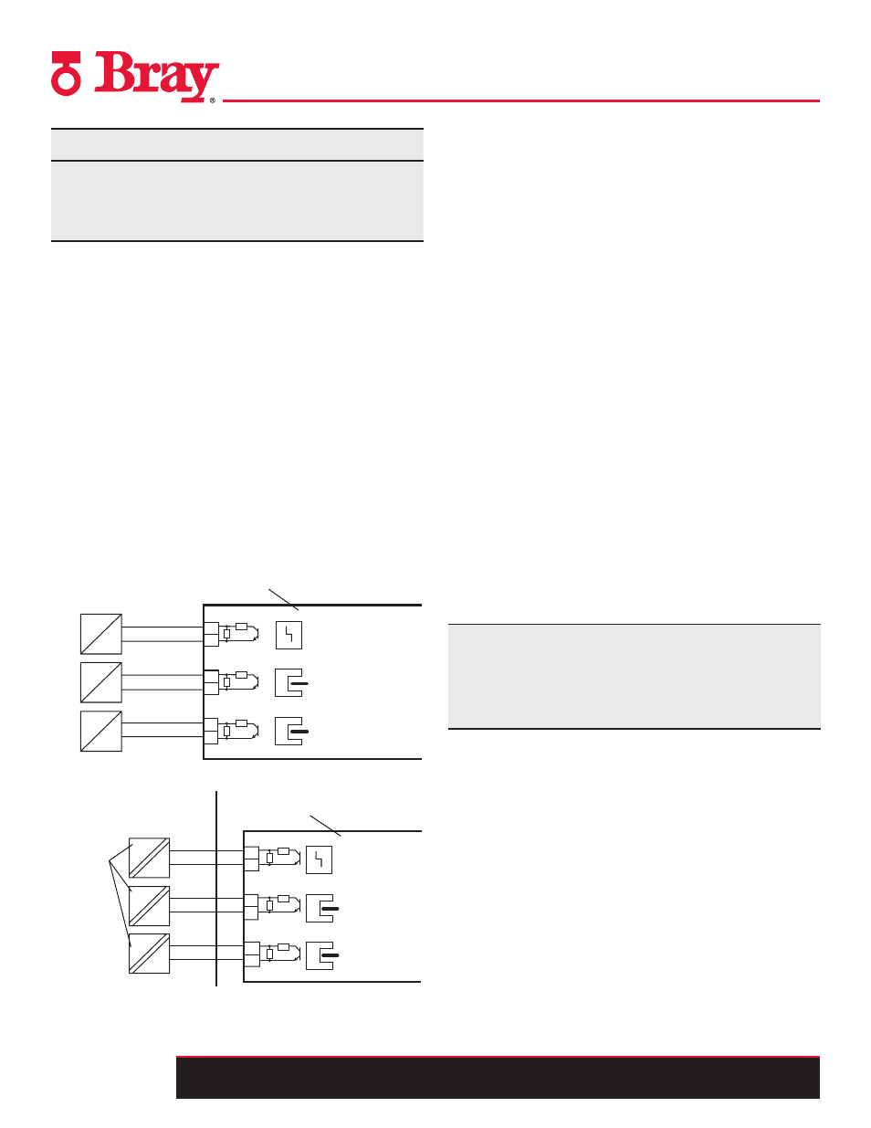
13. Refer to Figures 14 and 15 to connect the SIA module in stan-
dard and intrinsically safe applications
31
32
41
42
51
52
2K1
10K
< 35 V
8,2 V
8,2 V
+
+
+
Fault message
Limit value A1
Limit value A2
Switching amplifier according to EN 60947-5-6
SIA module
6DR4004-8G
#
#
#
31
32
41
42
51
52
8,2 V
8,2 V
8,2 V
SIA module
6DR4004-6G
Fault message
Limit value A1
Limit value A2
2K1
10K
Intrinsically safe
switching
amplifier to DIN
EN 60947-5-6
Non-hazardous area
Hazardous area, zone 1 or zone 2
EEx
EEx
EEx
+
+
+
#
#
#
Setting The Limits Of The Slotted Initiator Alarm Unit
You will require a suitable display device to determine the switch
status. For example, use the initiator tester type 2 / Ex by Pepperl
+ Fuchs.
1. Connect the display device to the following terminals of the
SIA unit:
• 41 and 42
• 51 and 52
2. Read the switch status of slotted initiators
Proceed as follows to set the limits:
1. Move the actuator to the first desired mechanical position.
2. Adjust the upper actuating disc manually until the output
signal at terminals 41 and 42 changes. Set a high-low or a
low-high switch over as follows:
• Rotate the actuating disc beyond the switching point
until you reach the next switching point.
3. Move the actuator to the second desired mechanical position.
4. Adjust the lower actuating disc manually until the output
signal at terminals 51 and 52 changes. Set a high-low or a
low-high switch over as follows:
• Rotate the actuating disc beyond the switching point
until you reach the next switching point.
Note: The actuating discs are relatively difficult to move. This
design prevents their unintentional movement during operation.
You can achieve an easier and finer adjustment by reducing
friction temporarily. Move the actuator to and fro while
simultaneously holding the actuating discs.
Figure 14 - SIA unit 6DR4004-8G, not Ex
Figure 15
-
SIA unit 6DR4004-6G, EEx i