Calibration and commissioning, Operation – Bray 6A Series O&M Manual User Manual
Page 11
All information herein is proprietary and confidential and may not be copied or reproduced without the expressed written consent of BRAY INTERNATIONAL, Inc.
The technical data herein is for general information only. Product suitability should be based solely upon customer’s detailed knowledge and experience with their application.
Series 6A Operation & Maintenance – Calibration & Commissioning
6A O & M : 11
CAlIbrATIOn AnD COMMISSIOnInG
Installing a New Unit
Please refer to the S6A Quick Start Guide for the Standard Unit.
Replacing a Unit
The S6A can be replaced in a running system where a S6A was
already in use without interrupting the process. By copying and
transferring the device and initialization data, it is possible to
commission a replacement positioner without needing to initial-
ize it. The S6A uses the communication interface to transfer data.
When this is performed, it is crucial to perform a standard initial-
ization of the replacement positioner as soon as possible because
the following properties can be ensured only after initializing:
• Optimum adjustment of the positioner as per the mechanical
and dynamic properties of the actuator.
• Unrestricted accuracy and dynamic behavior of the positioner.
• Deviation-free position of the hard-end stops.
• Accuracy of the maintenance data
Copy the initialization data and the device parameters as follows:
1. Read in the initialization data and the device parameters of the
positioner to be replaced. Use a suitable parameterization
tool for this purpose.
2. Save the data in the parameterization tool.
Note: If the positioner to be replaced has already been initialized
or configured using the parameterization tool, you need not read
in and save the device data.
Proceed as follows to replace a positioner in a running system:
3. Fix the actuator at its current position mechanically or
pneumatically.
4. Determine the actual position value.
– Read the actual position value on the digital display of
the positioner to be replaced.
Take note of the read value.
– If the electronic unit of the positioner is defective, mea-
sure the actual position value at the actuator or the valve.
Take note of the read value.
5. Dismantle the positioner.
6. Attach the lever arm of the positioner to be replaced to the
replacement positioner.
7. Install the replacement positioner on the control valve.
8. Set the transmission ratio selector of the replacement positioner
to the same position as that of the positioner to be replaced.
9. Use the parameterization tool to transfer the saved device and
initialization data to the replacement positioner.
10. If the displayed actual position value differs from the noted
value, correct the deviation by moving the friction clutch.
11. The replacement positioner is ready for operation when the
displayed and the noted values match.
Operation
Reading the LCD screen
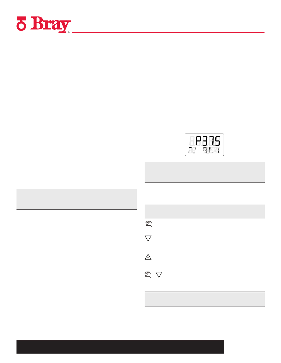
The S6A digital display has two lines, one on the bottom and one
on top. Each element on the top line has seven segments while
each element on the bottom line has fourteen. Contents of the dis-
play depend on the selected mode. Figure 6 below provides an
example of what the display will look like when the unit is pow-
ered on.
Note: When operated in temperature ranges below 14°F (-10°C),
the liquid crystal display of the positioner becomes sluggish and
the repetition rate display is reduced considerably.
Using the pushbuttons
The S6A is manually operated using three pushbuttons. The cover
of the positioner has to be removed in order to operate the buttons.
Note: The function of the buttons depends on the current
Operating Mode. As a general rule the following applies:
The operating mode button is used to select the modes and to
forward the parameters.
The decrement button is used to select parameter values when
configuring. You can use this button to move the actuator in
the manual mode.
The increment button is also used to select parameter values
when configuring. You can use the increment button to move
the actuator in the manual mode.
+
*Parameters are activated in the reverse order by press-
ing the operating mode button and the decrement button at
the same time
Note: The IP66/NEMA 4x degree of protection is not ensured
as long as the positioner is open.
Figure 6
Example Display