0 operation, 1 start-up and test, Operation 5.1 – Alpha Technologies GMX-915 User Manual
Page 29: Start-up and test
29
017-932-B0-002, Rev. B
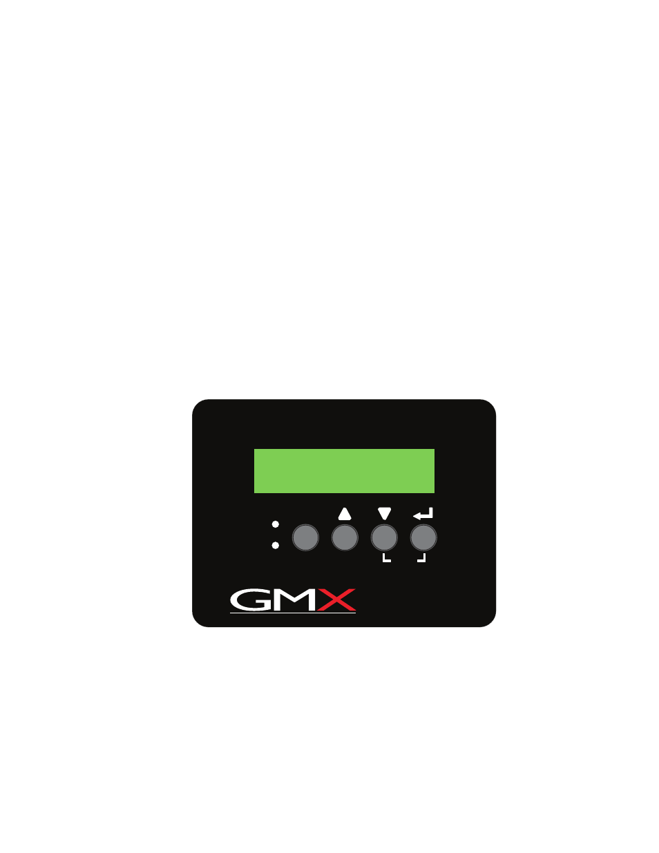
Fig. 5-1, Configuration Screen
5.0 Operation
5.1 Start-up and Test
AC Line Operation
1. Before making any power supply connections, verify the correct voltage, polarity, and
frequency are available from both the AC utility power source and the DC battery system.
2. Verify the AC circuit breaker (located on customer supplied service disconnect) and the
battery breaker on the GMX Power Supply are off.
3. Plug the GMX Power Supply power cord into the enclosure convenience outlet, and the
battery cable into the Battery Input connector on the front of the power supply. Plug the
RTS into the Temp Probe connection and attach it to the side of the center battery. If
applicable, connect the LRI wiring to the LRI ± terminals on the terminal block, and the
Auxiliary Output wiring to the AUX ± terminals on the terminal block.
4. Switch the AC (service disconnect) circuit breaker on to start initial power up. During
this stage the power supply performs a “display self-test”, and verifies the configuration
for the power supply. The configuration screen looks similar to the figure below. After
the initial display self-test, a No Batteries alarm message appears in the Smart Display
because the battery breaker is still off. The green output LED remains off, and the red
alarm LED continues to flash until the battery breaker is switched ON and the power
supply qualifies the batteries (this may take up to one minute).
OUTPUT
ALARM
ESC
TEST
OUTPUT FREQ BAT IN
90V 15A 50HZ 36V 225
S
E
R
I
E
S
5. Switch on the battery breaker. Within one minute the flashing red alarm LED turns OFF,
the green output LED turns ON, the No Battery alarm clears, and the power supply
resumes normal operation. Use the Smart Display to verify operations and Setup as
needed.