Explosion proof ls500e installation, Red) – Franklin Fueling Systems LS500 Auto Learn Line Leak Detection Installation & Users Guide User Manual
Page 8
8
Explosion Proof LS500E Installation
Note: The Explosion Proof 4-20mA Input Module has a RED face.
Warning
Lockout and tag circuit breakers, and disconnect console power wiring before installing or servicing
any system wiring.
Warning
DO NOT make transducer wiring connections with power connected to the console or any module.
Caution
Do not run intrinsically safe (IS) wiring and non-intrinsically safe (non-IS) wiring in the same
conduit.
Note: LS500E must be installed in accordance with the national electrical code, ANSI / NFPA 70, CEC or other applicable
national or local codes.
Note: The explosion-proof transducer needs to have explosion-proof conduit to the head of the transducer.
1. Pull the wiring through the explosion proof conduit that will be used for the TS-LSU500 transducers.
2. Mount the TS-LSU500E in the pump manifold.
3. The TS-LSU500E wiring must enter the console in Explosion Proof conduit through a knockout on the Hazardous
side of the barrier. Secure each pair of transducer wires to a single channel on the 4-20mA Input Module. Always
start at the first available channel and do not skip channels. For example, if channels one through three are
already being used for another application channel 4 must be used. Be sure to connect the wires to the correct
polarity (+/-). If the transducer is wired backwards it will not function.
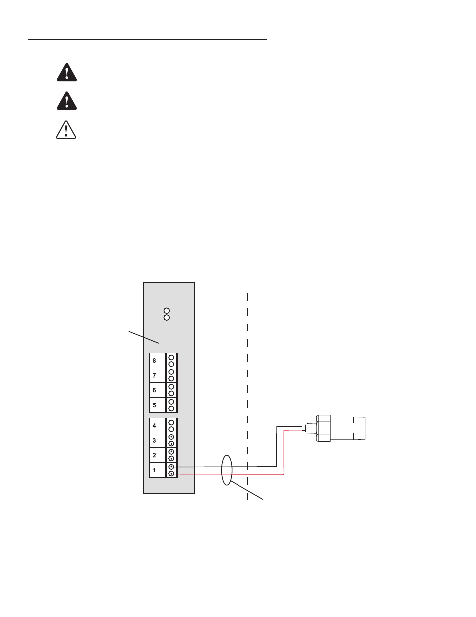
Figure 4 – 4-20 mA Input Module Wiring
4 - 20mA EXP
INPUT MODULE
RUN
ERR
–
+
–
+
–
+
–
+
–
+
–
+
–
+
–
+
- (BLK)
+ (RED)
Hazardous Location
Class I, Division 1, Group
D, Group IIA, Zone 0
Non-Intrinsically
Safe Side of
Console
(Red)
Explosion-Proof Conduit
LS-500E